
A direct-drive quadruped robot with variable leg configuration

A quadruped robot and configuration technology, applied in the field of robotics, can solve the problems of difficult control system design, inability to record joint zero position, increase leg inertia, etc. The effect of large swing speed

Active Publication Date: 2022-07-26
SHENYANG SIASUN ROBOT & AUTOMATION
View PDF9 Cites 0 Cited by
  • Summary
  • Abstract
  • Description
  • Claims
  • Application Information

AI Technical Summary

Problems solved by technology

There are mainly quadruped robots such as spotmini and anymal in foreign countries, and there are mainly quadruped robots such as laika and Jueying in China. All joints of spotmini are equipped with force / torque sensors to measure joint torque. Although the flexibility is high, the control system is complicated. It is difficult to realize, and the leg structure is single, only the full elbow configuration, and the practicability of different terrains is poor; anymal robot adopts 360° integrated joints, integrated motors, gears, springs, drivers, encoders and other components, which can Realize different leg configuration changes, high integration, complex structure, and difficult control system design. The knee joint of the leg is installed with an integrated joint, which increases the inertia of the leg and affects the frequency of leg swing; The frame motor is matched with a first-stage planetary reducer, the shoulder joint integrates 2 degrees of freedom, and the legs are driven by a link mechanism to achieve a low-inertia design. However, the leg configuration is single and unchangeable, and its adaptability to different terrains is limited.
[0003] Patent CN201510273183.3 discloses a small electric-driven bionic quadruped robot, which adopts the direct drive technology of AC permanent magnet synchronous motor and cancels the reducer. Although the structure is simple, the output torque is small, which is only suitable for the design of miniaturized robots, and the lower leg connecting rod Transmission, the leg configuration is only one kind of front elbow and back knee, the range of motion is limited, although the motion gait can be rich, but it lacks motion flexibility; patent CN201710093433.X discloses a quadruped robot single-leg mechanism, using a coreless motor With the large reduction ratio reducer transmission mechanism and the addition of external gear transmission and belt transmission, the rigidity of the leg structure must be very low, and the internal friction force is large, and the bandwidth of the pass frequency is low, which is not conducive to the realization of the joint force control algorithm; patent CN201710025569 .7 A single-axis two-degree-of-freedom robot joint is disclosed. This joint mainly solves the disadvantages brought about by the high reduction ratio that are not conducive to the realization of the joint force control algorithm. However, it only exists in theoretical analysis and does not completely solve this problem. First, the joint Only the Hall sensor in the motor stator is used to measure the joint angle. The Hall sensor has low control accuracy and cannot record the zero position of the joint. It needs to be reset when the power is turned on. There is a safety hazard that the zero position suddenly disappears after power on and off. This patent does not No homing mechanism or zero position sensor is mentioned; secondly, the motor rotor of the first degree of freedom of this joint is equipped with a first-stage planetary reducer, while the motor rotor of the second degree of freedom is directly installed with a pulley output, and the output of this degree of freedom rotates The torque is naturally not high, and it cannot bear the large load torque like the first degree of freedom, and the application occasions are limited; finally, the joint uses a pair of planetary reducer ball bearings, which has low space utilization and redundant structure

Method used


Image

  • A direct-drive quadruped robot with variable leg configuration
  • A direct-drive quadruped robot with variable leg configuration
  • A direct-drive quadruped robot with variable leg configuration

Examples


Embodiment Construction

[0040] The technical solutions of the present invention will be clearly and completely described below with reference to the accompanying drawings. Obviously, the described embodiments are a part of the embodiments of the present invention, but not all of the embodiments. Based on the embodiments of the present invention, all other embodiments obtained by those of ordinary skill in the art without creative efforts shall fall within the protection scope of the present invention.

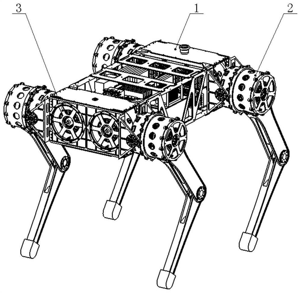
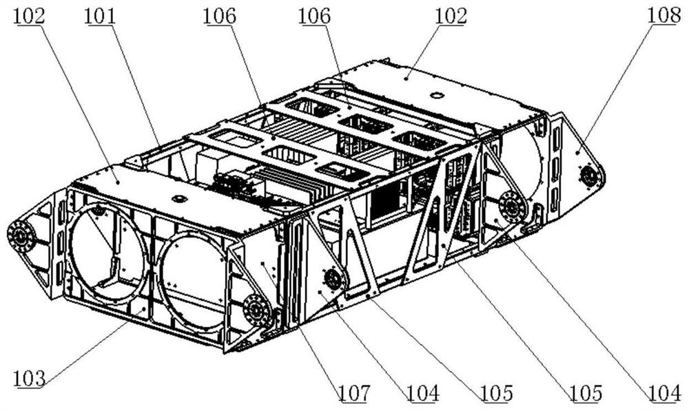
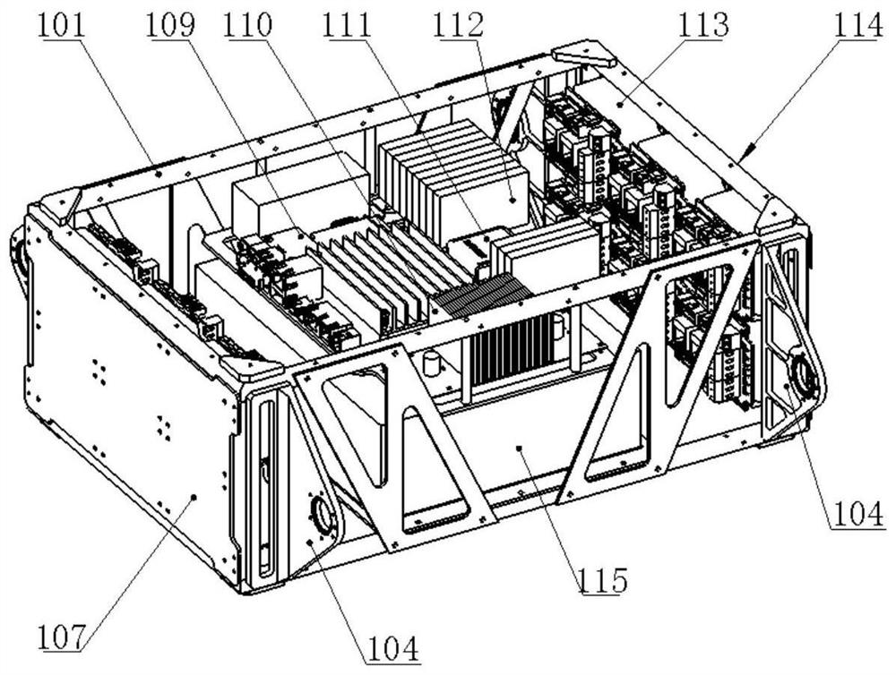
[0041] This embodiment provides a direct-drive quadruped robot with variable leg configuration, including a trunk 1, legs 2 and hips 3; the trunk 1 is used to install a control system and a power supply system 115, and the control system is used to control The action of the leg 2 and the hip 3, the power supply system 115 supplies power to the control system, the leg 2 and the hip 3; the leg 2 is rotated and connected to the outside of the trunk 1, and the thigh motor stator housing 218 of the leg 2 A...


PUM


Abstract

The present application relates to the technical field of robots, and specifically discloses a direct-drive quadruped robot with variable leg configuration, including a trunk, legs and hips; the legs are variable in configuration, including a full elbow type and a full knee type. , four configurations of front elbow and back knee, front knee and back elbow, realize the self-adaptation of leg configuration in multi-terrain environment, and realize the application of stairs, slopes, rugged road conditions, etc. Compared with the quadruped robot with immutable leg configuration, the present invention is more flexible, and can adapt to various road conditions such as on-load transportation, rough road conditions, slope steps, etc. It does not need to turn around when going up and down the stairs, and can change the configuration at any time to adapt to the environment. required, without multiple disassembly or modification of the leg mechanism.

Description

technical field [0001] The present application relates to the technical field of robots, in particular to a direct-drive quadruped robot with variable leg configuration. Background technique [0002] At present, there are more and more researches on quadruped robots, which have the characteristics of discontinuous support, so they can cross rough and complex terrain, taking into account the characteristics of flexibility, obstacle avoidance, multi-terrain adaptation, etc., and their practicability and applicability are better. Well, it has broad application prospects in military industry, inspection, logistics and other directions. There are mainly four-legged robots such as spotmini and anymal in foreign countries, and four-legged robots such as laika and Jueying in China. All the joints of spotmini are equipped with force / torque sensors to measure the joint torque. Although the flexibility is high, the control system is complex. It is difficult to implement, and the leg c...

Claims


Application Information

Patent Timeline
Patent Type & Authority Patents(China)
IPC IPC(8): B62D57/032
CPCB62D57/032
Inventor 马壮徐方于海亮唐冲赵鹏代涌泉
Owner SHENYANG SIASUN ROBOT & AUTOMATION
Learn More