Textile drawing effect strengthening device
A technology of strengthening device and mounting seat, applied in textile and paper making, spinning machine, continuous winding spinning machine, etc., can solve the problem of poor fiber straightness and separation, poor evenness, and small fiber bundles. There are other problems, to achieve the effect of reducing unevenness, deepening connection, and not easy to separate
- Summary
- Abstract
- Description
- Claims
- Application Information
AI Technical Summary
Problems solved by technology
Method used
Image
Examples
specific Embodiment approach 1
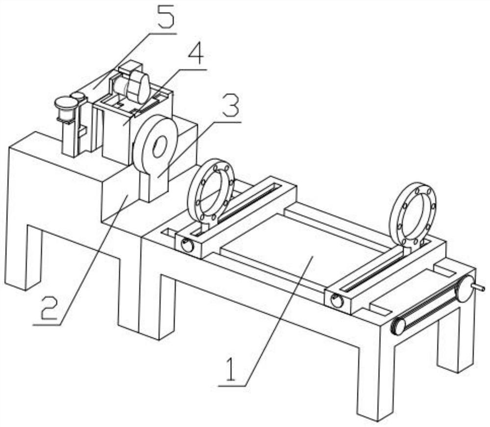
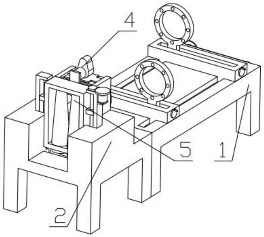
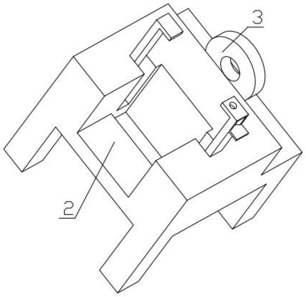
[0029] Combine below Figure 1-11 Describe this embodiment, a textile drawing frame effect enhancement device, including a plurality of adjustment mechanisms 1, a mounting seat 2, a preliminary gathering ring 3, an interlacing mechanism 4 and an adjustable drawing frame mechanism 5, the plurality of adjustment mechanisms 1 and The mounting base 2 is fixedly connected, and the preliminary gathering ring 3 is fixedly installed on the mounting base 2, and the interlacing mechanism 4 is fixedly installed on the mounting base 2, and the adjustable drawing frame mechanism 5 is fixedly installed on the mounting base 2.
specific Embodiment approach 2
[0031] Combine below Figure 1-11Describe this embodiment, this embodiment will further explain the first embodiment, the multiple adjustment mechanism 1 includes a base 1-1, a hand plate 1-2, a chain 1-3, a sprocket 1-4, and a sliding groove Plate one 1-5, multiple perforated rings one 1-6, screw hand plate one 1-7, multiple perforated rings two 1-8, sliding groove plate two 1-9, screw hand plate two 1-10, Threaded rod one 1-11, threaded rod two 1-12, sprocket two 1-13, sliding groove plate one 1-5 are slidably installed in the groove provided on the base 1-1, sliding groove plate two 1-9 slide Installed in the groove set on the base 1-1, multiple perforated rings 1-6 are slidably installed in the groove set on the sliding groove plate 1-5, and the screw hand crank plate 1-7 is rotatably installed in the sliding In the groove provided on the slot plate 1-5, multiple perforated rings 1-6 are threadedly connected with the screw hand plate 1-7, and multiple perforated rings 1-8...
specific Embodiment approach 3
[0033] Combine below Figure 1-11 Describe this embodiment, this embodiment will further explain the first embodiment, the interleaving mechanism 4 includes a fixed frame 4-1, a cam 4-2, a sliding plate 4-3, a push motor 4-4, and a pin 4-5 , support spring 4-6, the fixed frame 4-1 is fixedly installed on the mounting base 2, one end of the support spring 4-6 is fixedly installed on the fixed frame 4-1, and the other end of the support spring 4-6 is fixedly installed on the sliding plate On 4-3, the sliding plate 4-3 is slidably installed in the groove provided on the fixed frame 4-1, the pin 4-5 is fixedly installed on the sliding plate 4-3, and the push motor 4-4 is fixedly installed on the fixed frame On 4-1, the output end of the promotion motor 4-4 is fixedly equipped with a cam 4-2, and the cam 4-2 contacts with the sliding plate 4-3.
PUM
 Abstract
Description
Claims
Application Information
 - R&D
- Intellectual Property
- Life Sciences
- Materials
- Tech Scout
- Unparalleled Data Quality
- Higher Quality Content
- 60% Fewer Hallucinations
Browse by: Latest US Patents, China's latest patents, Technical Efficacy Thesaurus, Application Domain, Technology Topic, Popular Technical Reports.
© 2025 PatSnap. All rights reserved.Legal|Privacy policy|Modern Slavery Act Transparency Statement|Sitemap|About US| Contact US: help@patsnap.com


