Straw drying device utilizing induction heating and provided with double heating structures

A dual heating and induction heating technology, applied in heating devices, drying, dryers, etc., can solve the problems of insufficient drying effect, slow drying speed of straw, and rising temperature of heating plate, etc., to facilitate heating and drying. , good effect, large heating area

Inactive Publication Date: 2021-06-29
史玉芳
View PDF0 Cites 3 Cited by
  • Summary
  • Abstract
  • Description
  • Claims
  • Application Information

AI Technical Summary

Problems solved by technology

[0005] The object of the present invention is to provide a straw drying device with a double heating structure using induction heating to solve the problem that the existing straw drying device proposed in the background technology generally adopts the drying method of air drying or heating plate, wherein the air drying The temperature of the drying method i

Method used


Image

  • Straw drying device utilizing induction heating and provided with double heating structures
  • Straw drying device utilizing induction heating and provided with double heating structures
  • Straw drying device utilizing induction heating and provided with double heating structures

Examples


Embodiment example 1

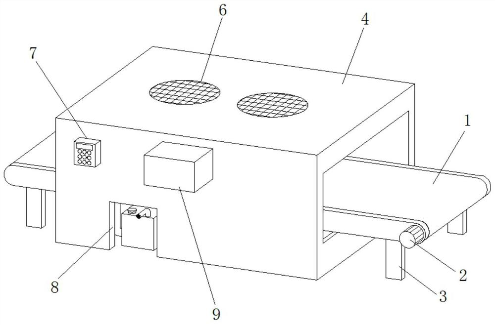
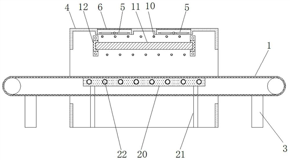
[0029] see Figure 1-3 , a straw drying device with a double heating structure using induction heating, comprising a conveyor belt mechanism 1 driven by a servo motor 2 fixedly installed on the right end side wall of the conveyor belt mechanism 1, the conveyor The lower surfaces of both ends of the belt mechanism 1 are fixedly equipped with a first support frame 3, and a protective cover 4 is arranged outside the middle position of the conveyor belt mechanism 1, and the top of the protective cover 4 is uniform along the length direction of the conveyor belt mechanism 1. Two fans 5 are fixedly installed, and a filter screen 6 is fixedly installed on the upper surfaces of the two fans 5, a control switch 7 is fixedly installed on the front left upper end of the protective cover 4, and a front lower end of the protective cover 4 is opened. There is a water tank mouth 8, and a low-frequency power supply 9 is fixedly installed in the middle position of the front upper end of the pr...

Embodiment example 2

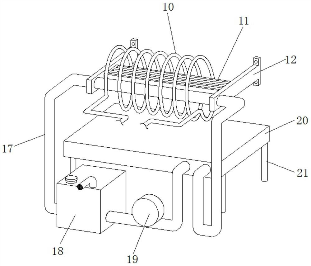
[0034] see Figure 5The circulation heating mechanism 13 includes a heating copper tube 16 fixedly installed on the outer ends of the two ceramic fixing frames 12 and arranged in the induction hollow copper tube coil 10 along the length direction of the conveyor belt mechanism 1. The heating copper tube 16 is The left end communicates with the water storage tank 18 , the water pump 19 and the heating plate 20 through the connecting copper pipe 17 in turn, and the heating plate 20 communicates with the right end of the heating copper pipe 16 through the connecting copper pipe 17 .

[0035] The heating copper pipe 16 of the circulating heating mechanism 13 can heat the water inside the heating copper pipe 16 under the induction heating effect of the induction hollow copper pipe coil 10 after electrification, and the heated water can circulate through the water under the circulation action of the water pump 19. The heating plate 20 is used to heat and dry the straw at the bottom....


PUM


Abstract

The invention discloses a straw drying device utilizing induction heating and provided with double heating structures. The straw drying device comprises a conveying belt mechanism, the conveying belt mechanism is driven by a servo motor fixedly installed on the side wall of the right end of the conveying belt mechanism, and first supporting frames are fixedly installed on the lower surfaces of the two ends of the conveying belt mechanism correspondingly. A protective cover is arranged on the outer side of the middle position of the conveying belt mechanism, two fans are evenly and fixedly installed on the top of the protective cover in the length direction of the conveying belt mechanism, filter screens are fixedly installed on the upper surfaces of the two fans, and a control switch is fixedly installed at the upper left end of the front face of the protective cover. A water tank opening is formed in the lower end of the front face of the protective cover, and a low-frequency power source is electrically connected with an induction hollow copper pipe coil fixedly arranged in the protective cover in the length direction of the conveying belt mechanism. The induction heating mode is adopted, the heating speed is high, the temperature is high, dual heating structures are adopted, and rapid drying and heating of straw can be achieved.

Description

technical field [0001] The invention relates to the technical field of straw recovery, in particular to a straw drying device with a dual heating structure using induction heating. Background technique [0002] Straw is the general term for the stem and leaf parts of mature crops. In order to avoid air pollution caused by straw burning, it is a better way to deal with straws by baling and bundling straws for centralized transportation and recycling. Straw needs to be dried before recycling. [0003] Existing straw drying devices generally adopt air drying or heating plate drying methods, and the air drying drying method has a lower temperature, so the drying speed of straw is slower and the drying effect is not thorough enough; while the heating plate drying method The method is limited by the slow temperature rise of the heating plate, and the heating plate can only heat and dry the straw from one side (such as the bottom), which leads to low drying efficiency. [0004] ...

Claims


Application Information

Patent Timeline
IPC IPC(8): F26B15/18F26B21/00F26B23/10
CPCF26B15/18F26B21/001F26B23/10F26B2200/02
Inventor 史玉芳
Owner 史玉芳
Why Eureka
Try Eureka