Charging chip, charging device and mobile terminal
A charging chip and charging device technology, which is applied to battery circuit devices, circuit devices, electric vehicles, etc., can solve the problems of occupying a processor universal asynchronous transceiver bus interface, increasing production costs, and level conversion circuit occupying circuit board area, etc. Achieve the effect of reducing resource overhead and the number of traces, reducing costs, and saving circuit board area
- Summary
- Abstract
- Description
- Claims
- Application Information
AI Technical Summary
Problems solved by technology
Method used
Image

Examples
no. 1 example
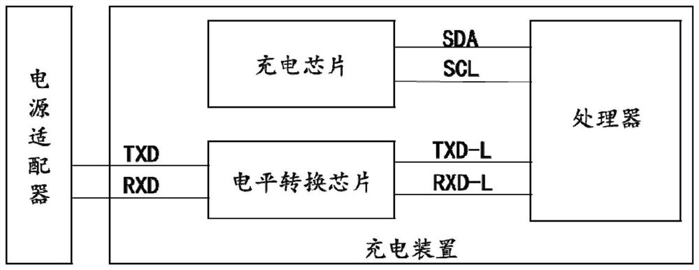
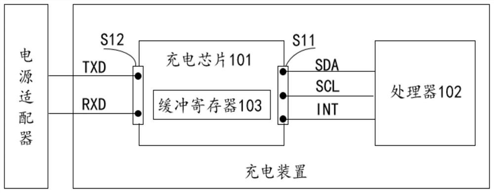
[0037] figure 2 It is a schematic structural diagram of the charging device provided in Embodiment 1 of the present application. The charging device of the present application is set in the mobile terminal and is used to charge the rechargeable battery of the mobile terminal, such as figure 2 As shown, the first interface and the second interface of this embodiment are represented by S11 and S12 respectively. The charging device of the present application includes: a charging chip 101 and a processor 102;
[0038] The charging chip 101 includes a first interface and a second interface;
[0039] The charging chip 101 communicates with the processor 102 through the first interface;
[0040] The charging chip 101 communicates with the power adapter through the second interface, and the second interface is a Universal Asynchronous Receiver Receiver Bus (UART) interface.
[0041] Optionally, the second interface of the charging chip 101 adopts 3.3V CMOS level or 5V TTL level. ...
no. 2 example
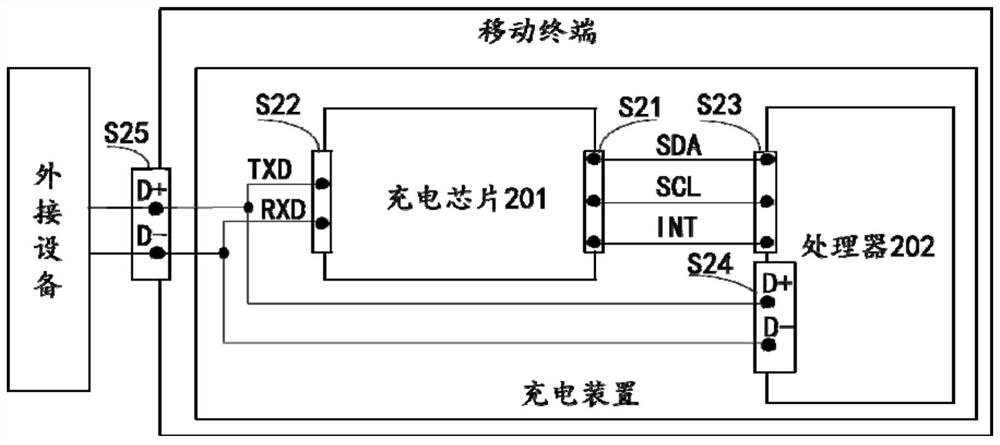
[0059] image 3 It is a schematic structural diagram of the charging device provided in Embodiment 2 of the present application. Such as image 3 As shown, S21, S22, S23, S24, and S25 represent the first interface, the second interface, the third interface, the fourth interface, and the charging interface of the mobile terminal in this embodiment respectively. The charging device of the present application includes: a charging chip 201. Processor 202;
[0060] The charging chip 201 includes a first interface and a second interface;
[0061] The processor 202 includes a third interface and a fourth interface;
[0062] The first interface of the charging chip 201 is connected to the third interface of the processor 202 .
[0063] Wherein, the second interface of the charging chip 201 is a universal asynchronous transceiver bus interface.
[0064] Optionally, the second interface of the charging chip 201 is connected to the charging interface of the mobile terminal, and is c...
no. 3 example
[0076] Figure 4 It is a schematic structural diagram of the charging device provided in Embodiment 3 of the present application. Such as Figure 4 As shown, the first interface, the second interface, the third interface, the fourth interface, and the charging interface of the mobile terminal are represented by S31, S32, S33, S34, and S35 respectively. The charging device of the present application includes: a charging chip 301. Processor 302;
[0077] The charging chip 301 includes a first interface and a second interface;
[0078] The processor 302 includes a third interface and a fourth interface;
[0079] The first interface of the charging chip 301 is connected to the third interface of the processor 302;
[0080] Wherein, the second interface of the charging chip 301 is a universal asynchronous transceiver bus interface.
[0081] Optionally, the processor 302 obtains and identifies the type of the external device connected to the charging interface of the mobile ter...
PUM
 Abstract
Description
Claims
Application Information
 - R&D
- Intellectual Property
- Life Sciences
- Materials
- Tech Scout
- Unparalleled Data Quality
- Higher Quality Content
- 60% Fewer Hallucinations
Browse by: Latest US Patents, China's latest patents, Technical Efficacy Thesaurus, Application Domain, Technology Topic, Popular Technical Reports.
© 2025 PatSnap. All rights reserved.Legal|Privacy policy|Modern Slavery Act Transparency Statement|Sitemap|About US| Contact US: help@patsnap.com