
Robot movement mechanism

A motion mechanism and robot technology, applied in the field of robots, can solve the problems of large external size, large size, and large space occupation, and achieve the effect of reducing overall size and manufacturing cost, improving stability and reliability, and reducing space occupation.

Inactive Publication Date: 2021-07-02
DELU DYNAMICS TECH (CHENG DU) CO LTD
View PDF0 Cites 0 Cited by
  • Summary
  • Abstract
  • Description
  • Claims
  • Application Information

AI Technical Summary

Problems solved by technology

[0003] However, due to the complex structure, large size and high cost of the electromagnetic brake, the existing kinematic mechanism has a large external dimension, high cost, and takes up a lot of space, so that the existing kinematic mechanism cannot be used in light Quantify on low-cost devices

Method used


Image

  • Robot movement mechanism
  • Robot movement mechanism
  • Robot movement mechanism

Examples


Embodiment Construction

[0029] In order to better understand the present invention, the present invention will be further described below with reference to the accompanying drawings and examples. Obviously, the described embodiments are merely embodiments of the invention, not all of the embodiments. In the case of an unable conflict, the features and embodiments in the present invention can be combined with each other.

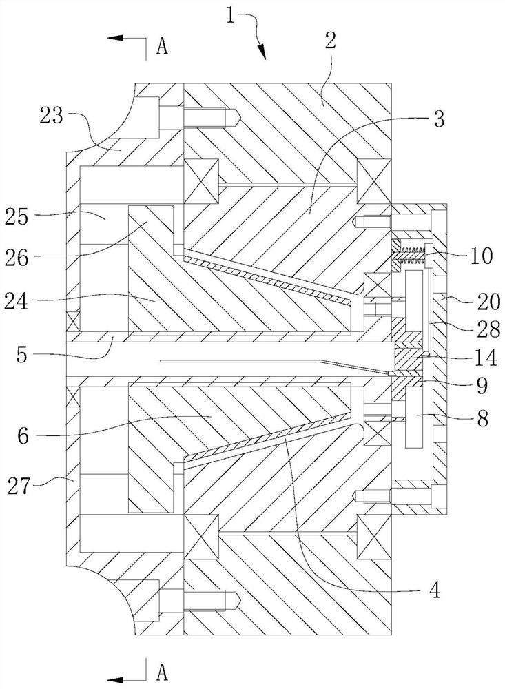
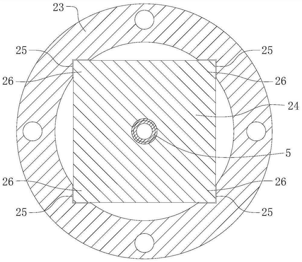
[0030] figure 1 It is a schematic structural diagram of a robot motion mechanism according to an embodiment of the present invention; figure 2 Yes figure 1 A cross-sectional view of the A-A.

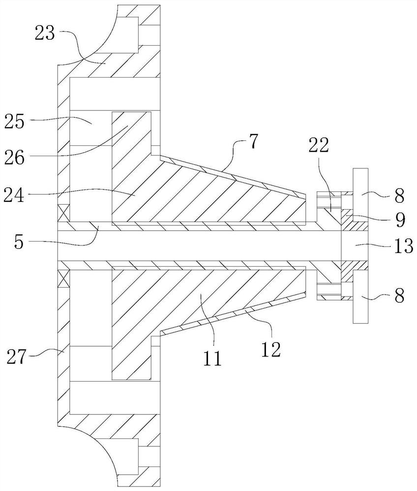
[0031] See figure 1 , figure 2 , The robot moving mechanism provided by the embodiment of the present invention, includes a motor 1; the motor 1 includes a motor stator 2 and a motor rotor 3; the center of the motor rotor 3 has two ends opening, and a circular stage brake 4; The brake cavity 4 has a brake shaft 5 provided with the motor rotor 3, and the front end of the brake shaft 5 rotates thro...


PUM


Abstract

The invention relates to the technical field of robots, and provides a robot movement mechanism. The robot movement mechanism comprises a motor, wherein a brake cavity is formed in the center of a motor rotor; a brake shaft which is coaxial with the motor rotor is arranged in the brake cavity; the front end of the brake shaft is rotatably connected with the motor rotor through a bearing; a circular truncated cone-shaped brake component which is in threaded connection with the brake shaft is arranged in the brake cavity; a guiding rotation stopping device is arranged on the rear side of the motor; a brake disc is arranged on the front side of the motor; and a brake driving component which is arranged on the motor rotor is also arranged on the front side of the motor. The brake cavity is formed in the motor rotor, and the brake component which is matched with the brake cavity is arranged in the brake cavity, so that the brake component is accommodated in the brake cavity, the size of the robot movement mechanism in the axial direction is reduced, the space occupied by the robot movement mechanism is reduced, and the robot movement mechanism can be applied to light-weight low-cost equipment.

Description

Technical field [0001] The present invention relates to the field of robots, in particular a robotic motion mechanism. Background technique [0002] At present, the movement of the robot's head and the mechanical arm joint is achieved by a motion mechanism composed of the main motor and electromagnetic brake brake. For the movement of the robot's head, the main motor drives the head rotation, and brakes the rotation shaft of the main motor by electromagnetic brake brake, so that the head remains in the current relative position. For the movement of the mechanical arm joint, the main motor drives the mechanical limb joint to the predetermined angle relative to another mechanical limb joint, and brake is carried out by electromagnetic brake brake to the main motor, so that the two mechanical limbs remain in Current relative angles. [0003] However, due to the complex structure of the electromagnetic brake brake, the size is large, the cost is high, causing the existing motion mech...

Claims


Application Information

Patent Timeline
Patent Type & Authority Applications(China)
IPC IPC(8): B25J19/00H02K1/12H02K1/22H02K7/10
CPCB25J19/00H02K1/12H02K1/22H02K7/10
Inventor 李学生龚迪琛马凡钟
Owner DELU DYNAMICS TECH (CHENG DU) CO LTD
Learn More