Fixed-length slitting device for strip brush machining
A technology of fixed length and strip brush, which is applied in the field of fixed length slitting devices for strip brush processing, can solve the problems of low efficiency and labor consumption, and achieve the effects of high cutting quality, improved efficiency, and improved application scope.
- Summary
- Abstract
- Description
- Claims
- Application Information
AI Technical Summary
Problems solved by technology
Method used
Image
Examples
Embodiment 1
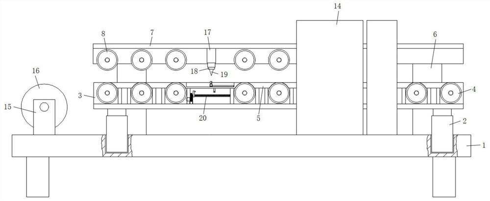
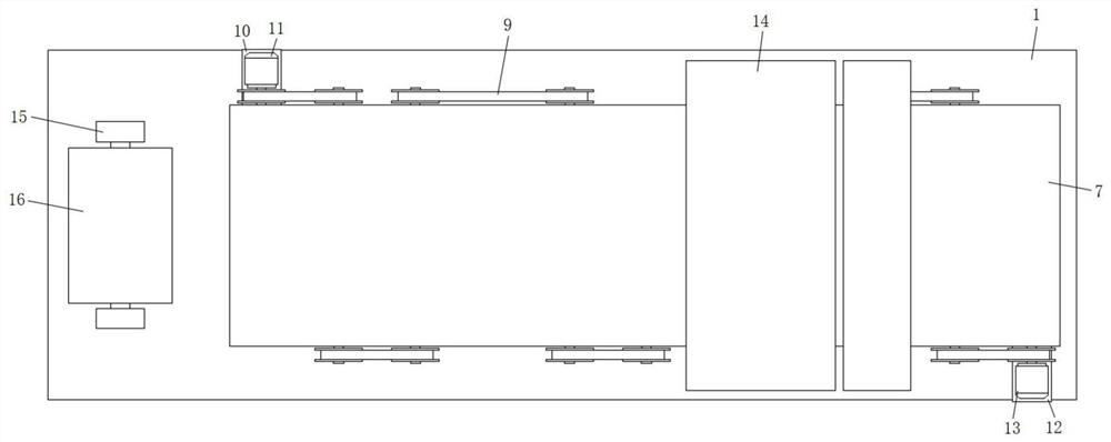
[0031] refer to Figure 1-4, a fixed-length cutting device for strip brush processing, including a processing table 1, a cylindrical hole is provided on one side of the top surface of the processing table 1, and four cylindrical holes are arranged on the top surface of the processing table 1 in a rectangular shape. The inner bottom surface of the hole is fixedly connected with the cylinder 2 by screws, and the output end of the cylinder 2 is provided with a conveying dish-3 through screws, and the front and rear inner walls of the conveying dish-3 are rotatably connected with a conveying roller-4, and the inner bottom surface of the conveying dish-3 is also fixedly connected with a The support table 5 and the cylinder 2 are welded with fixed columns 6 on the side facing away from the center of the processing table 1. The tops of the four fixed columns 6 are fixedly connected with the conveying dish 2 7 by screws, and the front and rear inner walls of the conveying dish 2 7 are ...
Embodiment 2
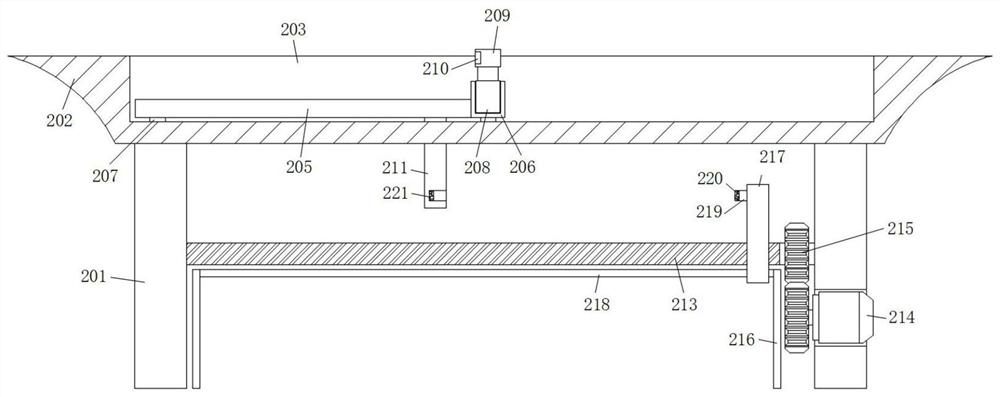
[0034] Such as image 3 As shown, this embodiment is basically the same as Embodiment 1. Preferably, a limit bar 219 is fixed on the side near the center of the cutting table 202 at the upper end of the push bar 217, and a limit groove is provided on one side of the push plate 211, and one end of the limit bar 219 The first magnet 220 and the second magnetic strip 221 are respectively fixed on the side wall of the limiting groove.
[0035] The limiting strip 219 is on the same level as the center of the limiting groove, and the magnetic properties of the first magnet 220 and the second magnetic strip 221 are opposite.
[0036] In this embodiment, the servo motor three 214 drives the screw rod 213 to rotate to make the push bar 217 move toward the push plate 211. When the push bar 217 is close to the push plate 211, the magnet one 220 and the magnetic strip two 221 interact to make The steel sheet comes out from the material receiving groove 210, and then the electric telescop...
Embodiment 3
[0038] Such as Figure 4 As shown, this embodiment is basically the same as Embodiment 1. Preferably, the output terminals of the control switch 1 226 and the control switch 2 227 are electrically connected to the control terminal of the electric telescopic rod 1 17 and the control terminal of the servo motor 3 214 respectively.
[0039] In this embodiment, the first control switch 226 and the second control switch 227 are electrically connected to the first electric telescopic rod 17 and the third servo motor 214, so as to facilitate the control of the working states of the first electric telescopic rod 17 and the third servo motor 214.
PUM
 Abstract
Description
Claims
Application Information
 - R&D
- Intellectual Property
- Life Sciences
- Materials
- Tech Scout
- Unparalleled Data Quality
- Higher Quality Content
- 60% Fewer Hallucinations
Browse by: Latest US Patents, China's latest patents, Technical Efficacy Thesaurus, Application Domain, Technology Topic, Popular Technical Reports.
© 2025 PatSnap. All rights reserved.Legal|Privacy policy|Modern Slavery Act Transparency Statement|Sitemap|About US| Contact US: help@patsnap.com


