
Eureka
For R&D, Eureka makes reading and utilizing patents & technical documents easy.
Eureka AIR
Designed for self-driven R&D workflows. Generate viable solutions, solve complex R&D challenges, empower your innovation with AI.

Eureka Materials
Designed for material experts only. Revolutionize your material R&D, from search, analyze, to developing new materials.

TechResearch
Generate reliable direction feasibility study reports for your R&D in just a few steps.

TechSeek
Discover and master advanced knowledge NOW. Basics, ideas, possibilities, all at once.

TechMind
As an expert in R&D Theories, TechMind can generates customized viable solutions instantly.

TechRisk
Analyze your overall solution with one click, know your potential R&D risks in advance.

TechMonitor
Get weekly tech updates, stay abreast of the latest tech innovations and key insights.
Overload protector for main drive speed reducer of shield tunneling machine, and shield tunneling machine
An overload protector and reducer technology, applied in the direction of automatic clutch, clutch, mechanical equipment, etc., can solve the problems of the main drive of the shield machine, the overload protection mechanism of the reducer can not be used, and achieve accurate fracture position, small occupied space, The effect of avoiding damage
- Summary
- Abstract
- Description
- Claims
- Application Information
AI Technical Summary
Problems solved by technology
Method used
Image

Examples
Embodiment 2
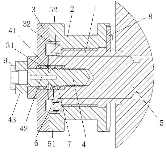
[0043] Embodiment 2: The safety bolt 4 is covered with a spring 7, and the spring 7 is arranged between the torque shaft 5 and the end cover 3, and the two ends of the spring 7 are in contact with the torque shaft 5 and the end cover 3 respectively, so that After the torque shaft 5 is disconnected from the end cover 3, the torque shaft 5 is bounced to one side of the motor to avoid friction with the end cover 3 to cause damage. Specifically, the torque shaft 5 and the end cover 3 are respectively provided with spring slots for accommodating the spring 7, wherein the torque shaft 5 is provided with a torque shaft spring slot 51, the end cover 3 is provided with an end cover spring slot, and the two ends of the spring 7 are respectively Butt the end away from the two torque slots. Moreover, the spring 7 is compressed when it is sleeved on the safety bolt 4 and packed between the two spring grooves, so that it has a pre-tightening force to spring the torque shaft 5 to one side of...
Embodiment 3
[0044] Embodiment 3: The safety bolt 4 is provided with a fracture reminder structure for reminding when the safety bolt 4 is broken due to overload.
[0045] Further, the fracture reminder structure includes a cavity 42 axially arranged on the safety bolt 4, the cavity 42 is arranged on the side of the safety bolt 4 close to the end cover 3, the outer end of the cavity 42 is open, and passes through The plug 9 with transparent material is closed, so that the inside of the cavity can be seen through the transparent material. The cavity 42 is provided with a colored liquid, which may be yellow or red and other eye-catching liquid. The length that the cavity 42 extends in the safety bolt 4 is greater than the length of the pre-opening stress groove 41 from the outer end of the safety bolt 4, that is, the length of the cavity crosses the position where the safety bolt 4 is provided with the pre-opening stress groove 41, so that the safety bolt 4 After the position of the pre-ope...
Embodiment 4
[0046] Embodiment 4: The end of the torque shaft 5 close to the protector housing passes through the motor shaft 1, and a bearing 6 is arranged between the torque shaft 5 and the sleeve 2, and the bearing 6 and the sleeve 2 are in clearance fit, and the bearing 6 Interference fit with sleeve 2. Specifically, an annular groove is arranged at one end of the sleeve 2 near the end cover 3, so that there is an annular space between the end of the sleeve 2 and the torque shaft 5, and a bearing 6 is arranged in the annular groove, and the bearing is sleeved on the torque shaft. shaft 5, but there is a certain gap between the bearing and the torque shaft 5 so that the torque shaft has a space to disengage from the end cover 3; To the role of bearing 6 axial positioning. And after disengagement, the effect of the bearing between the torque shaft 5 and the sleeve 2 can rotate relatively, and avoid the radial displacement of the torque shaft, and avoid the damage caused by the collision...
PUM
 Abstract
Description
Claims
Application Information
 - R&D Engineer
- R&D Manager
- IP Professional
- Industry Leading Data Capabilities
- Powerful AI technology
- Patent DNA Extraction
Browse by: Latest US Patents, China's latest patents, Technical Efficacy Thesaurus, Application Domain, Technology Topic, Popular Technical Reports.
© 2024 PatSnap. All rights reserved.Legal|Privacy policy|Modern Slavery Act Transparency Statement|Sitemap|About US| Contact US: help@patsnap.com