Micro-droplet fluorescence signal detection device with biconvex lens

A fluorescence signal detection and fluorescence signal technology, which is applied in measuring devices, fluorescence/phosphorescence, and material analysis through optical means, can solve the problems of large space occupation, slow detection speed, and single spatial structure, and reduce installation and debugging. Difficulty, convenience of installation and debugging, and the effect of improving detection efficiency

Inactive Publication Date: 2021-07-02
TARGETINGONE TECH (BEIJING) CORP
View PDF5 Cites 1 Cited by
  • Summary
  • Abstract
  • Description
  • Claims
  • Application Information

AI Technical Summary

Problems solved by technology

[0003] In terms of detection methods, it can be divided into two types: CCD time-sharing photography and laser single-point frequency division detection. Compared with laser single-point scanning systems, CCD photography has a simpler structure, shorter development cycle, and lower technical difficulty. The detection speed is slow, the cost is high, the sensitivity is low, and the space occupied is large. In future applications, it is limited by the diversity of biological samples and the performance of the instrument itself, so it is difficult to apply in large-scale batches.
In the traditional laser confocal detection device, the detection optical path is to eliminate the interference of stray light outside the focal plane and improve the detection sensitivity. A pinhole is set at the receiving end, and its spatial structure is single and fixed. Whether it is single laser, double laser or multi-laser Excitation signal detection devices all have disadvantages such as a fixed increase in the number of pinholes, an increase in the number of lasers used for excitation light, an increase in the optical path, and a high requirement for the integrity of the detection device from the laser to the signal collection end. Because the increase in the number of pinholes makes debugging more difficult Large, which virtually increases the signal receiving error of the device. When performing multi-channel signal detection, part of the signal is attenuated and lost due to the increase of the spatial optical path, and the corresponding detection signal is lost. The high integrity requirements are not convenient for product assembly. and post-maintenance

Method used


Image

  • Micro-droplet fluorescence signal detection device with biconvex lens
  • Micro-droplet fluorescence signal detection device with biconvex lens
  • Micro-droplet fluorescence signal detection device with biconvex lens

Examples


Embodiment Construction

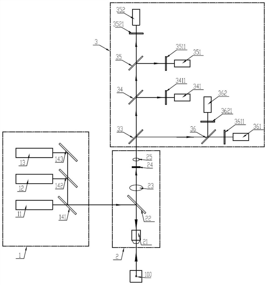
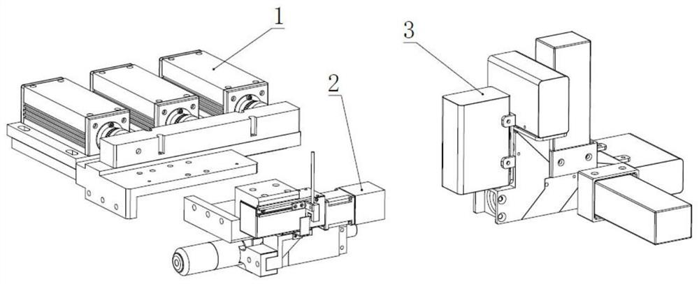
[0026] see in conjunction Figure 1 to Figure 5 As shown, according to an embodiment of the present invention, a micro-droplet fluorescent signal detection device with a lenticular lens is provided, including:

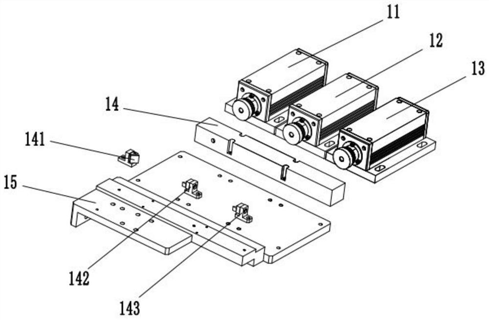
[0027] The light source module 1 is used for synthesizing different lasers with different wavelengths into mixed excitation light;

[0028]The light combination module 2 includes an objective lens 21, a first dichroic mirror 22, a first convex lens 23, a small hole 24, and a second convex lens 25; The light is reflected into the objective lens 21, and the objective lens 21 can focus the mixed excitation light on the micro-droplet 100 to be detected to excite and generate a plurality of different fluorescent signals corresponding to different laser light; the first convex lens 23, The pinhole 24 and the second convex lens 25 collimate multiple different fluorescent signals into parallel light;

[0029] The signal receiving module 3 is connected to the output end of th...


PUM


Abstract

The invention provides a micro-droplet fluorescence signal detection device of a biconvex lens. The micro-droplet fluorescence signal detection device comprises a light source module for synthesizing different lasers with different wavelengths into mixed exciting light; a light combination module comprises an objective lens, a first dichroscope, a first convex lens, a small hole and a second convex lens; the first dichroscope reflects the mixed exciting light emitted by the light source module into the objective lens, and the objective lens can focus the mixed exciting light on a micro-droplet to be detected; the first convex lens, the small hole and the second convex lens collimate a plurality of different fluorescence signals into parallel light; and a signal receiving module is connected with the output end of the light combination module and is used for receiving the fluorescence signal output by the light combination module. According to the invention, a double-lens single-aperture light path conduction structure is adopted, so that collimated parallel light can be formed, signal detection cannot be influenced by increase of an optical path, the loss of a fluorescence signal can be effectively reduced, only one aperture is provided and does not need to be increased along with increase of the number of detection channels, and the installation and debugging difficulty is greatly reduced.

Description

technical field [0001] The invention belongs to the technical field of microfluidic detection chips, and in particular relates to a micro-droplet fluorescence signal detection device with a biconvex lens. Background technique [0002] Biochips are widely used in new drug development, disease diagnosis and gene expression analysis. Microfluidic detection chip technology is becoming more and more mature, and has gradually become a hot spot of people's attention. There are various biological and chemical processes in the microfluidic detection chip, and the process is usually completed in the micron-scale flow channel space, which requires some devices that can detect the reaction process. [0003] In terms of detection methods, it can be divided into two types: CCD time-sharing photography and laser single-point frequency division detection. Compared with laser single-point scanning systems, CCD photography has a simpler structure, shorter development cycle, and lower technic...

Claims


Application Information

Patent Timeline
Patent Type & Authority Applications(China)
IPC IPC(8): G01N21/64G01N21/01
CPCG01N21/6402G01N21/01
Inventor 黄海旺夏雷于海侠周跃梁欢迎白宇杨文军
Owner TARGETINGONE TECH (BEIJING) CORP
Why Eureka
Try Eureka