
Laser shock peening device and method for welding seam part of spaceflight propellant storage tank

A laser shock strengthening and propellant technology, which is applied in laser welding equipment, welding equipment, non-electric welding equipment, etc., can solve the problems of large gaps in weld stress distribution, high price, lack of laser shock strengthening equipment, etc.

Pending Publication Date: 2021-07-06
BEIHANG UNIV
View PDF11 Cites 1 Cited by
  • Summary
  • Abstract
  • Description
  • Claims
  • Application Information

AI Technical Summary

Problems solved by technology

Most of the existing laser shock peening equipment is only suitable for small components or flat plate components with relatively simple structures. For some workpieces with various weld forms and complex impact paths, it is usually necessary to use expensive flexible light guide arms, and it is difficult to apply to size Larger component reinforcement
Aerospace propellant tanks have various sizes and there are long friction stir welding seams and fusion welding girth welds. Because the welding methods used by the two types of welds are completely different in principle, the softening zone position and stress distribution state of the weld seams are quite different. A scientific and reasonable laser shock strengthening equipment and matching strengthening method can effectively strengthen the welding area of ​​the tank

Method used


Image

  • Laser shock peening device and method for welding seam part of spaceflight propellant storage tank
  • Laser shock peening device and method for welding seam part of spaceflight propellant storage tank
  • Laser shock peening device and method for welding seam part of spaceflight propellant storage tank

Examples


Embodiment

[0080] In this embodiment, the material of the aerospace propellant storage tank is 2219 aluminum alloy, the diameter of the storage tank is 2m, and the total length is 6m. Two long friction stir welding seams with a width of 20mm and three fusion welds with a width of 15mm are required on the outside of the storage tank. Girth welds are laser shock peened.

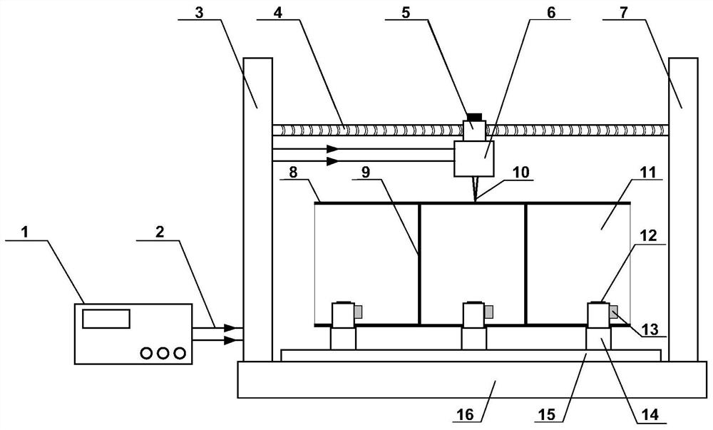
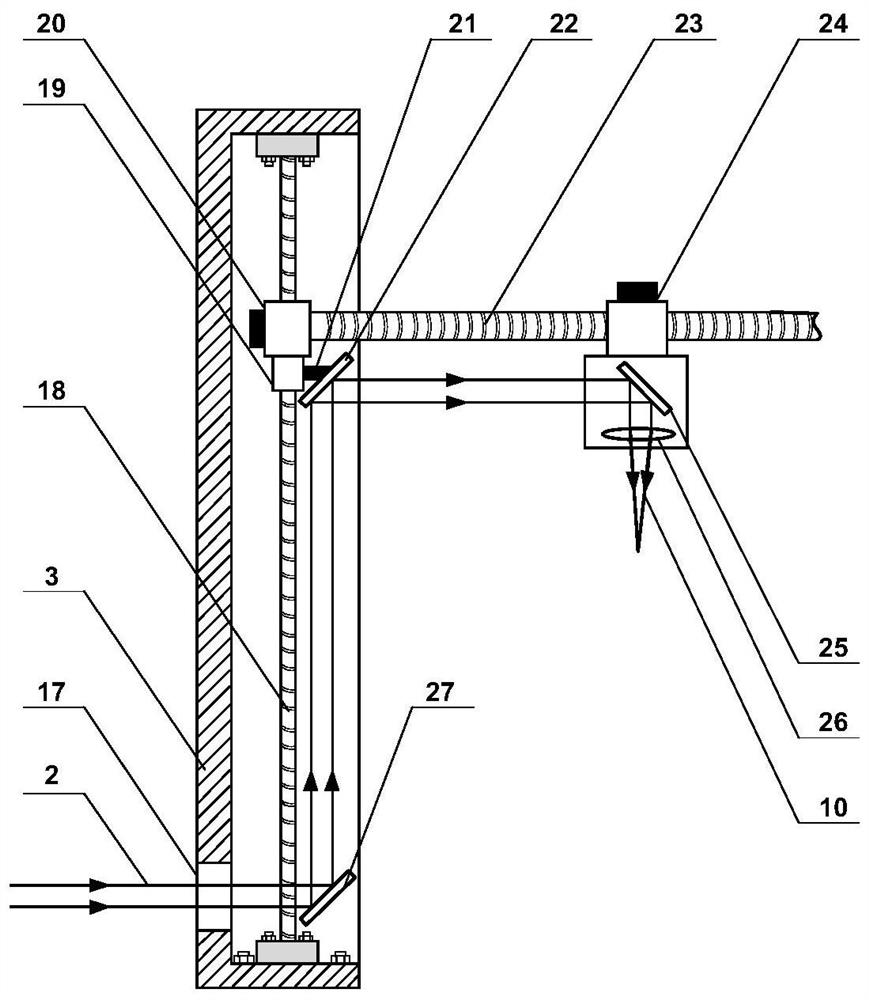
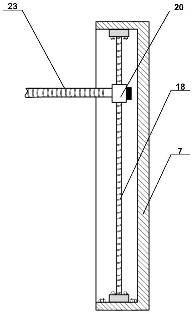
[0081] Adjust the relative positions of the six roller load-bearing brackets 14 on the mobile platform 15 to ensure that the aerospace propellant storage tank 11 can be placed stably. Start the vertical motion stepping motor 20 to drive the horizontal lead screw 23 to move, adjust the height of the laser focusing head 6 to move 2.4m from the mobile platform, start the mobile platform 15, and move horizontally on the working platform 16 to ensure that the storage tank does not collide with the horizontal wire when hoisting. After the bar 4 interferes, the aerospace propellant storage tank 11 is placed on six roller load-be...


PUM


Abstract

The invention provides a laser shock peening device and method for a welding seam part of a spaceflight propellant storage tank. The laser shock peening device comprises a storage tank moving assembly and a laser shock peening assembly. The storage box moving assembly controls the spaceflight propellant storage box to rotate in the circumferential direction. A laser focusing head moving structure of the laser shock peening assembly is provided with a laser focusing head, and the laser focusing head is controlled to move along a fixed path; a laser propagation light path structure propagates parallel laser beams emitted by a laser device to the laser focusing head; and the laser beams focused by the laser focusing head act on a welding area where a friction stir welding long welding seam and a fusion welding circumferential welding seam of the spaceflight propellant storage tank are located for shock peening. By means of the laser shock peening device and method, according to friction stir welding and fusion welding heat input characteristics, impact areas of different sizes are selected for different welding seams for laser impact peening, the internal dislocation density of a welding seam softening area material is increased, the tensile property and reliability of a joint are improved, a participating pressure stress field is generated in a welding seam area, and the service life of the whole spaceflight propellant storage tank is prolonged.

Description

technical field [0001] The invention relates to the technical field of laser shock strengthening of the weld surface, in particular to a laser shock strengthening device and method for the welding seam of an aerospace propellant tank. Background technique [0002] The propellant storage tank is widely used in the field of aerospace manufacturing. Its main structure is an aluminum alloy cylindrical tank. Usually, friction stir welding is used for long straight seam welding, and then multi-section cylindrical tanks are spliced. Seam welding joins it as a whole. During the aluminum alloy welding process, the grains will coarsen in a certain width area on both sides of the weld, and the strengthening phase dispersed in the base metal will also dissolve and coarsen, forming a softening zone. The softening zone is usually the weakest area in the aluminum alloy welded joint. It has low hardness and is prone to concentrated strain, which seriously reduces the overall mechanical pro...

Claims


Application Information

Patent Timeline
IPC IPC(8): B23K26/356B23K26/24B23K20/12
CPCB23K20/122B23K26/24B23K26/356
Inventor 郭伟戴为张宏强朱颖
Owner BEIHANG UNIV
Learn More