Antenna for improving influence of surface waves and increasing beamwidth

A surface wave and antenna technology, applied in the direction of antenna, antenna coupling, antenna array, etc., can solve the problems of asymmetric radiation field, instability, difficult orientation and so on

Pending Publication Date: 2021-07-06
ARCADYAN
View PDF0 Cites 0 Cited by
  • Summary
  • Abstract
  • Description
  • Claims
  • Application Information

AI Technical Summary

Problems solved by technology

In other words, the multiple radiating components at two adjacent receiving ends are very close to each other, which will produce a strong coupling effect, resulting in an asymmetric and unstable radiation field, and an asymmetric and unstable phase difference, making it more difficult to accurately determine the orientation of an object

Method used


Image

  • Antenna for improving influence of surface waves and increasing beamwidth
  • Antenna for improving influence of surface waves and increasing beamwidth
  • Antenna for improving influence of surface waves and increasing beamwidth

Examples


Embodiment Construction

[0111] The implementation of the present invention will be described in more detail below in conjunction with the drawings and component symbols, so that those skilled in the art can implement it after studying this specification.

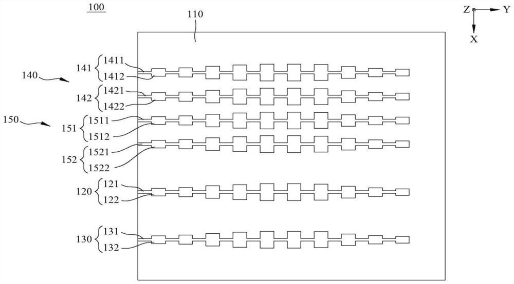
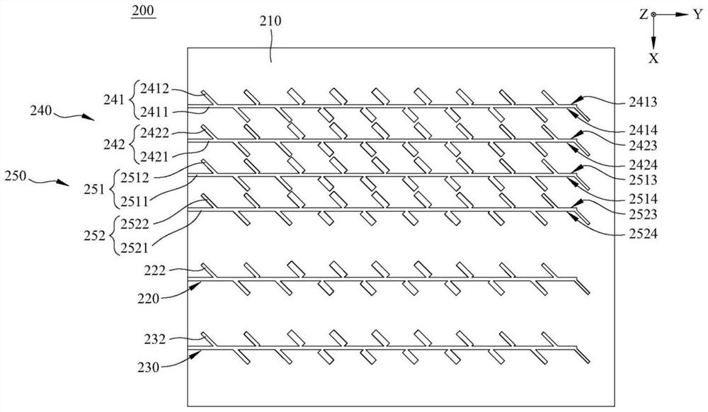
[0112] see Figure 5 to Figure 9 , are respectively a perspective view, a front view, a left side view, a top view and a right side view of the first embodiment of the present invention. The present invention provides an antenna 1 for improving surface wave influence and increasing beam width, including a substrate 10 , a first metal ground 20 , a second metal ground 30 , a transmitting end 40 and a receiving module 50 .

[0113] The two surfaces of the substrate 10 in a Z-axis direction are respectively defined as a first surface 101 and a second surface 102, and the two sides of the substrate 10 in a Y-axis direction are respectively defined as a first side 11 and a second side. Two sides 12 , the two sides of the substrate 10 in an X-axis direc...


PUM


Abstract

Provided is an antenna for improving an influence of surface waves and increasing a beamwidth, which includes: a substrate, a first metal ground, a second metal ground, an emitting end and a receiving module. The first metal ground and the second metal ground are disposed on a first surface of the substrate. The second metal ground is completely separated from the first metal ground by a first gap. The emitting end is disposed on the first metal ground and includes a transmission line and a plurality of radiating elements. The receiving module is disposed on the second metal ground and includes a first receiving end and a second receiving end. The first receiving end includes a transmission line and a plurality of radiating elements. The second receiving end includes a transmission line and a plurality of radiating elements. In such a way, the antenna of the present invention can solve mutual interference of electromagnetic waves between the emitting end and the receiving module, and achieve the purpose of improving an influence of surface waves, thereby improving the accuracy in determining the direction of an object by the antenna of the present invention.

Description

technical field [0001] The invention relates to an antenna, in particular to an antenna for improving the influence of surface waves and increasing beam width. Background technique [0002] In order to improve driving safety, current vehicles are equipped with blind spot detection, lane switch assist, automatic distance control cruise, parking assist, automatic braking, collision warning, lane departure detection and other systems. The above systems are usually equipped with a vehicle radar capable of accurately and reliably detecting and locating surrounding objects in any environment. The vehicle radar includes an antenna. The antenna usually uses the principle of frequency modulated continuous wave (FMCW) to detect the distance and speed of the object. Its operating frequency can be 24GHz, 77GHz or 79GHz to support the frequency band of the vehicle radar. [0003] see figure 1 , figure 1 is a top view of the first known antenna 100 . The first known antenna 100 includ...

Claims


Application Information

Patent Timeline
Patent Type & Authority Applications(China)
IPC IPC(8): H01Q1/52H01Q25/00
CPCH01Q1/521H01Q25/001H01Q1/3233H01Q1/525H01Q21/065H01Q21/068H01Q13/206G01S7/03G01S13/32G01S13/58H01Q1/38H01Q1/48
Inventor 李冠毅郭信郎
Owner ARCADYAN
Why Eureka
Try Eureka