Composite power synchronous control method and system for voltage source converter

A voltage source type, synchronous control technology, applied in the direction of reactive power compensation, single-grid parallel feeding arrangement, etc., can solve the problems of poor synchronization effect of synchronous loop, synchronous frequency resonance, poor system stability, etc.

Active Publication Date: 2021-07-06
SHANGHAI JIAO TONG UNIV
View PDF4 Cites 0 Cited by
  • Summary
  • Abstract
  • Description
  • Claims
  • Application Information

AI Technical Summary

Problems solved by technology

In this control strategy, the synchronous loop integrates twice, so even if the damping is large, the phase margin is not large, and the system stability is poor
Furthermore, a damping factor is intr...

Method used


Image

  • Composite power synchronous control method and system for voltage source converter
  • Composite power synchronous control method and system for voltage source converter
  • Composite power synchronous control method and system for voltage source converter

Examples


Embodiment 1

[0081] A compound power synchronous control system of a voltage source converter provided according to the present invention includes:

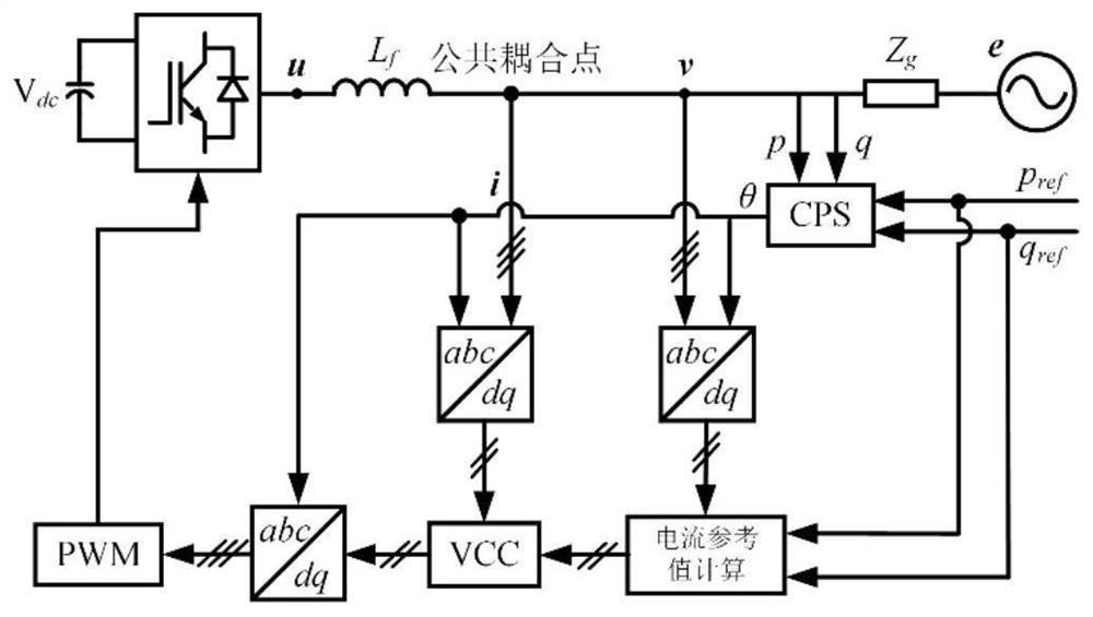
[0082] Module M1: DC voltage source V dc After the output voltage u of the converter, and then through the filter L f Through the AC source impedance Z g Connected to the AC power supply e, measure the filter L f The common coupling point voltage v and the line current i at the connection point with the AC power supply e;

[0083] Module M2: Calculate the actual active power p and reactive power q according to the common coupling point voltage v and line current i at the connection point;

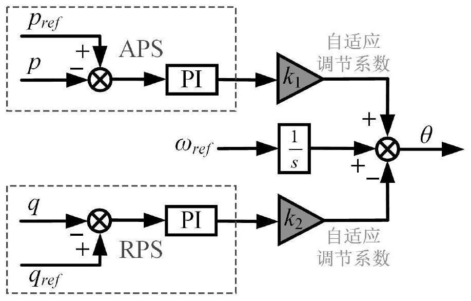
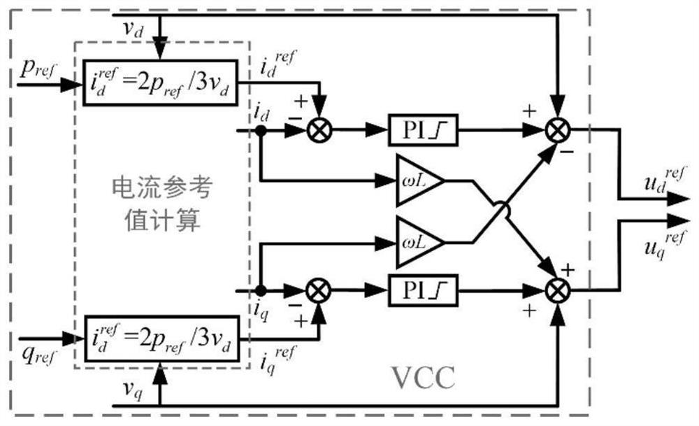
[0084] Module M3: based on actual active power p, reactive power q, preset active power power command p ref and the preset reactive power q ref , through the compound power synchronous loop CPS to calculate the reference angle θ required for Parker transformation or Parker inverse transformation coordinate transformation;

[0085] Module M4: Based on...

Embodiment 2

[0138] Embodiment 2 is a preferred example of embodiment 1

[0139] In order to realize the independent control of the power of the converter system, the voltage source converter and the connected system need to be kept in sync. Considering various working states such as strong and weak power grids and island connections, the present invention is suitable for voltage source converters Composite power synchronous control method. The invention does not need a phase-locked loop, and can realize system synchronization under any working condition; there is no resonance peak at the grid frequency, which enhances system stability; it has the ability to limit fault current and protect switching devices.

[0140] The invention relates to a synchronous control method for a voltage source converter system based on compound power. The overall control structure is as figure 1 Shown, including composite power synchronous loop and vector current loop. The system operation objectives inclu...

Embodiment 3

[0167] Embodiment 3 is a preferred example of embodiment 1 and / or embodiment 2

[0168] The existing converter synchronization technology is still dominated by various forms of phase-locked loops. This scheme proposes a composite power synchronization control method for voltage source converters, which avoids the negative effects of phase-locked loops on converters. influences. According to the present invention, a converter system based on a composite power synchronous control method is built, and the converter system is as follows: Figure 4 shown. The steady-state operation target of the converter system is to stabilize the active power and reactive power at the reference value.

[0169] like Figure 7 As shown, the initial state active power and reactive power are close to 0. At the moment of 0.2s, the active power reference value is increased to 84.45kW, the active power reaches the steady-state value within 0.02s, and the reactive power has been stable at the initial...


PUM


Abstract

The invention provides a composite power synchronous control system and method for a voltage source converter, and the method comprises the steps: enabling a DC voltage source Vdc to output a voltage u through the converter, enabling the DC voltage source Vdc to be connected with an AC power supply e through a filter Lf, and measuring a common coupling point voltage v and a line current i at a connection point of the Lf and the e; calculating actual active power p and reactive power q; based on the power p, the power q, the preset work power pref and the preset reactive power qref, calculating a reference angle theta required by Park transformation or Park inverse transformation coordinate transformation; transforming the voltage v and the current i from a three-phase static coordinate system to a two-phase rotating coordinate system according to the reference angle theta to obtain transformed vd and vq and transformed id and iq; calculating a current reference value according to vd and vq; calculating a reference voltage required by PWM modulation according to id, iq and a current reference value; and converting the reference voltage from a two-phase rotating coordinate system to a three-phase static coordinate system according to the reference angle theta, and providing a control signal for the converter through a PWM link.

Description

technical field [0001] The present invention relates to the field of power electronics, in particular to the control of voltage source converters, and in particular to a compound power synchronous control method and system for voltage source converters. Background technique [0002] As the mainstream interface equipment for distributed energy generation systems to connect weak power grids and island systems, voltage source converters can not only provide reactive power support for the connected systems, have black start capabilities, but also reduce cable costs. [0003] For voltage source converters, the commonly used control methods are active angle control and vector current control. [0004] Power angle control is relatively simple and easy to implement. It controls the active power by adjusting the phase angle difference between the voltage source converter and the connected system, and controls the reactive power by adjusting the voltage amplitude of the voltage sourc...

Claims


Application Information

Patent Timeline
IPC IPC(8): H02J3/40H02J3/48H02J3/50
CPCH02J3/40H02J3/48H02J3/50Y02E40/30
Inventor 朱淼陈哲侯川川徐莉婷蔡旭
Owner SHANGHAI JIAO TONG UNIV
Why Eureka
Try Eureka