
Magnetic gathering type magnetic coupler

A magnetic coupler and magnetic focusing technology, applied in the direction of permanent magnet clutch/brake, electric brake/clutch, electrical components, etc., can solve the problem that the rotation speed is easily affected by the load and the environment, and the transmission ratio of the motor and the working machine cannot be accurate. Control, slow response of the working machine, etc.

Pending Publication Date: 2021-07-06
周宇
View PDF1 Cites 0 Cited by
  • Summary
  • Abstract
  • Description
  • Claims
  • Application Information

AI Technical Summary

Problems solved by technology

[0006] In order to make up for the existing technology, although the power transmission is realized through magnetic coupling, it solves the problem that the rotating shaft has no inertial rotation and the load is large during the starting process of the motor. Problem, but the existing magnetic coupler, after the motor starts, the working machine responds slowly, and the working machine needs to rotate for a period of time before the working machine can run normally. At the same time, the transmission ratio between the motor and the working machine cannot be accurately controlled during the rotation process. , during the working process, the rotation speed of the working machine is easily affected by the load and the environment. For the equipment that requires a high speed and uniform speed during normal operation, it cannot be used.

Method used

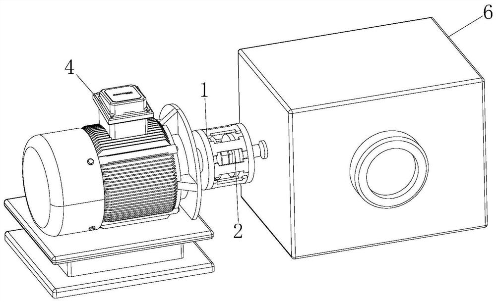
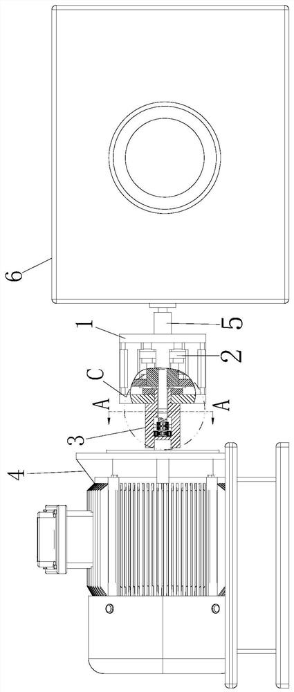
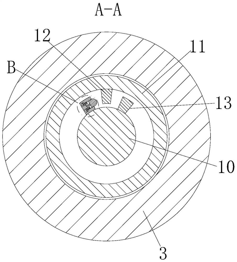

Image

  • Magnetic gathering type magnetic coupler
  • Magnetic gathering type magnetic coupler
  • Magnetic gathering type magnetic coupler

Examples


Embodiment approach

[0032] As an embodiment of the present invention, the notch direction of the adjustment groove and the corresponding second tooth block 9 are designed vertically; the adjustment blocks 17 are all slid perpendicular to the direction corresponding to the second tooth block 9; the A third spring is firmly connected between the adjustment block 17 and the groove bottom of the corresponding adjustment groove; during operation, the adjustment block 17 is axially slid by making the movement direction of the adjustment block 17 perpendicular to the corresponding second tooth block 9 , to avoid the direct radial sliding design, the adjustment block 17 is susceptible to centrifugal force, even if the operation of the working machine 6 is blocked, the centrifugal force of the adjustment block 17 will prevent the adjustment block 17 from retracting, affecting the response of the adjustment block 17, This reduces the response sensitivity of the device.

[0033] As an embodiment of the pres...


PUM


Abstract

The invention belongs to the technical field of transmission in mechanical engineering, and particularly relates to a magnetism gathering type magnetic coupler which comprises a conductive rotor and a permanent magnet rotor. The side surface of the conductive rotor is fixedly connected with a first connecting block; the interior of the conductive rotor is rotationally connected with a permanent magnet rotor; the side surface of the permanent magnet rotor is fixedly connected with a second connecting block; the surface of the second connecting block is fixedly connected with a core rod; the surface of the core rod is in sliding connection with a first tooth block; and the inner surface of the first connecting block is fixedly connected with a second tooth block. Automatic switching between magnetic transmission and mechanical transmission of the magnetic coupler is effectively achieved, it is guaranteed that adjustment can be conducted through magnetic coupling in the initial starting stage of the motor, the problems that the load is high in the initial starting stage of the motor, and the motor is overheated and even burnt down are solved, and meanwhile during stable operation, the working machine can operate stably and accurately, and the operation stability of the working machine is guaranteed.

Description

technical field [0001] The invention belongs to the technical field of transmission in mechanical engineering, in particular to a magnetism-gathering magnetic coupler. Background technique [0002] Magnetic couplings are also called magnetic couplings and permanent magnet transmissions. Permanent magnet eddy current transmissions are mainly composed of copper rotors, permanent magnet rotors and controllers. Generally, the copper rotors are connected to the motor shaft, and the permanent magnet rotors are connected to the working There is an air gap between the copper rotor and the permanent magnet rotor, and there is no mechanical connection for torque transmission. [0003] According to CN107276368A, an adjustable-speed magnetic-gathering double-tube asynchronous magnetic coupler, in the present invention, the torque is transmitted through the driving rotor and the driven rotor without contact, avoiding friction, wear and vibration during transmission of the mechanical coup...

Claims


Application Information

Patent Timeline
IPC IPC(8): H02K49/10
CPCH02K49/106
Inventor 周宇
Owner 周宇
Learn More