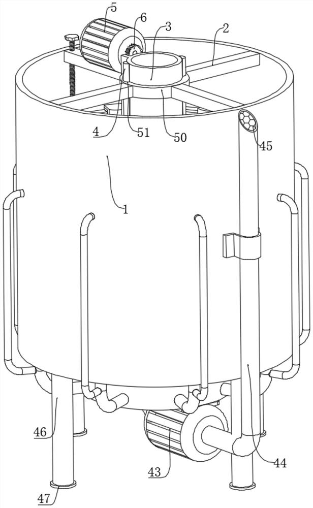
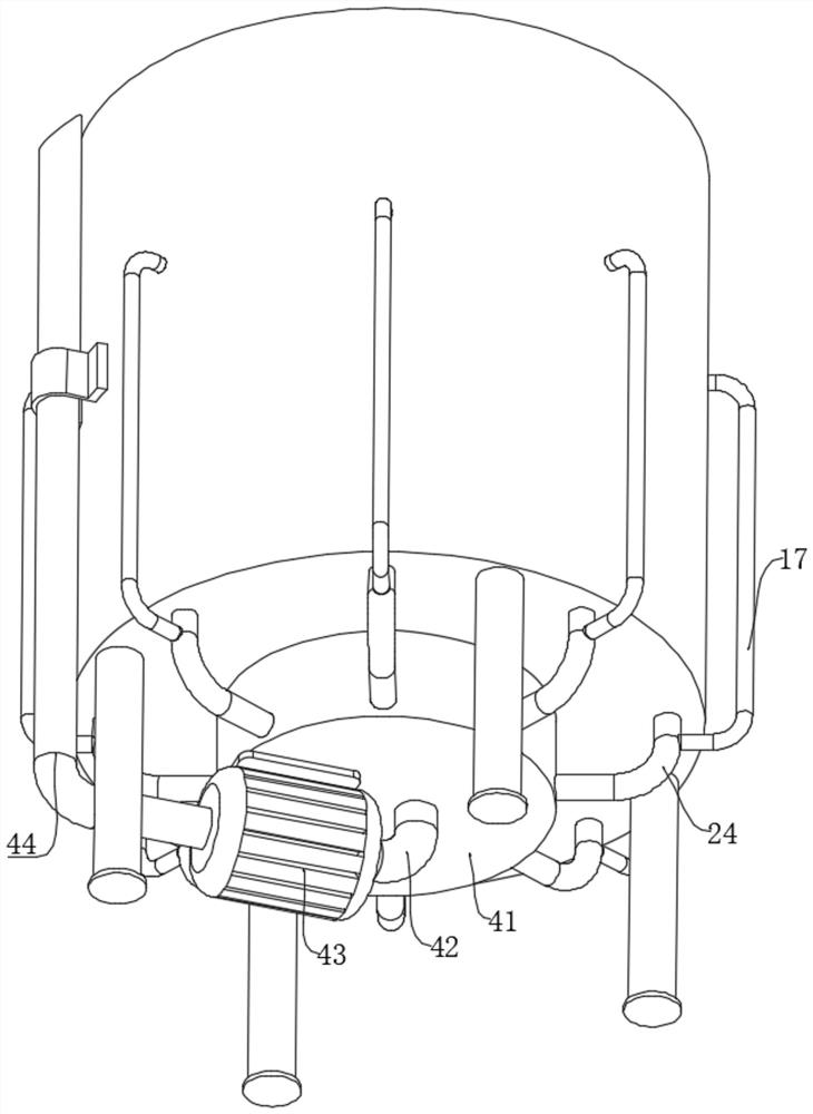
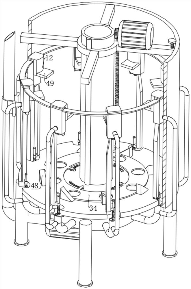
A petrochemical oil-water separation device

An oil-water separation device and petrochemical technology, applied in the petroleum industry, separation methods, filtration and separation, etc., can solve the problems of reducing the oil-water separation effect, the deterioration of the oil-water separation effect of the produced fluid, and the deterioration of the oil-water separation effect. The area of ​​floating separation is comprehensive, reducing the range of oil droplets and improving the effect of passing range

Active Publication Date: 2022-07-01
张志伟
View PDF6 Cites 0 Cited by
  • Summary
  • Abstract
  • Description
  • Claims
  • Application Information

AI Technical Summary

Problems solved by technology

[0003] In the field of petrochemical industry, in addition to crude oil and water, the oil well production fluid often contains rock debris, clay particles, scale deposits, corrosion products, and rock debris extracted from the oil reservoir. Mechanical impurities such as clay particles, scale deposits, and corrosion products are easily adsorbed on the oil-water interface, thereby hindering the coalescence between oil droplets and water droplets, and making the oil-water separation effect of the produced fluid worse; polymers with high water content will make The increase in the viscosity of the water phase of the produced liquid will slow down the floating rate of the oil droplets in the produced liquid with high water content, and the oil-water separation effect will become poor. Therefore, it is necessary to filter the solids in the mixed liquid before the oil-water separation. During the operation, it is difficult to completely remove the solids in the oil-water mixture. During the process of floating and stratifying the oil and gas in the water by the air flotation method, when the oil and gas particles touch the solid particles in the mixed liquid during the rising process, Bubbles generated by oil and gas particles are easy to break during contact, thereby reducing the effect of oil-water separation

Method used


Image

  • A petrochemical oil-water separation device
  • A petrochemical oil-water separation device
  • A petrochemical oil-water separation device

Examples


Embodiment approach

[0033] As an embodiment of the present invention, a single air intake mechanism includes a plurality of movable rods 23, and the movable rods 23 are located under each connection housing 11 respectively. One side of the top of the movable rod 23 is a tangential structure, and the top of the movable rod 23 The other side is fixedly connected with the second circular rod 20, one end of the second circular rod 20 is fixedly connected with the second baffle plate 21, the bottom of the connection shell 11 is fixedly connected with the first connecting ring 19, the second The circular rods 20 are all sleeved in the adjacent first connecting rings 19 , the second circular rods 20 between the first connecting ring 19 and the movable rod 23 are all sleeved with second springs 22 , and the lower part of the movable rod 23 One side of each of the adjacent arc-shaped grooves 31 is in contact with the adjacent arc groove 31, the other side below the movable rod 23 is fixedly connected with ...


PUM


Abstract

The invention relates to the technical field of oil-water separation, in particular to a petrochemical oil-water separation device. One end is fixedly connected to the inner wall of the layered barrel, a connecting ring is connected in the collar through a rotation limiting mechanism, a vertical lifting mechanism is connected to the connecting ring, a filter plate is slidably sealed at the bottom of the surface of the connecting ring, and the side walls of the filter plate and The inner walls of the layered barrel are in sliding contact. In this technical solution, after the air bubbles rise to the bottom of the filter plate, they will rise out through the connection between the filter plate and the connecting ring and the arc groove on the side of the filter plate, and reach the layered place, thereby effectively reducing the air bubbles in the rising process. The probability of solid particles contacting and breaking is conducive to separating oil droplets with smaller diameters from the water body below and improving the effect of oil-water separation.

Description

technical field [0001] The invention relates to the field of oil-water separation, in particular to a petrochemical oil-water separation device. Background technique [0002] Oil-water separation is mainly based on the difference in density or chemical properties of water and oil, using the principle of gravity sedimentation or other physicochemical reactions to remove impurities or complete the separation of oil and water. Air flotation is a method that relies on the formation of tiny air bubbles in water, which carry flocs and float to the liquid surface to purify water. The condition is that air bubbles attached to oil droplets can form oil and gas particles. Since the appearance of bubbles increases the density difference between water and particles, and the particle diameter is larger than that of crude oil droplets, replacing oil density with particle density can significantly increase the rising speed. Publication number CN112408546A discloses a petrochemical oil-wa...

Claims


Application Information

Patent Timeline
Patent Type & Authority Patents(China)
IPC IPC(8): B01D17/035B01D36/00C10G33/00
CPCB01D17/0205B01D36/006C10G33/00
Inventor 张志伟张文利赵乃超张李龙
Owner 张志伟
Why Eureka
Try Eureka