
Workholding device for robot deburring workstation

A clamping device and deburring technology, which is applied in positioning devices, metal processing machinery parts, clamping, etc., can solve the problems of workpiece clamping and positioning, affecting the effect of deburring, and poor working environment, etc., so as to achieve less space occupation , improve the positioning effect, the effect of compact structure

Active Publication Date: 2022-06-21
WUXI BEST PRECISION MACHINERY
View PDF9 Cites 0 Cited by
  • Summary
  • Abstract
  • Description
  • Claims
  • Application Information

AI Technical Summary

Problems solved by technology

[0003] After the machining of machine parts is completed, there will be a large number of burrs at the intersection of the processing surface and the non-processing surface, or at the intersection of two processing features; the existence of burrs will bring hidden dangers to safety and function, so the burrs need to be removed. For workpieces with complex shapes and many internal channels, the burrs are generally removed manually, and the manual deburring method not only has a harsh working environment, but also has a high work intensity. Therefore, it is better to use robot deburring instead of manual deburring. Can improve the processing environment and reduce labor intensity
[0004] However, when the robot clamps the workpiece, due to the fixed positioning points, it is easy to have one or several positioning points not touching the workpiece, which will affect the clamping and positioning of the workpiece and easily affect the deburring process. Effect

Method used


Image

  • Workholding device for robot deburring workstation
  • Workholding device for robot deburring workstation
  • Workholding device for robot deburring workstation

Examples


Embodiment Construction

[0041] In order to make the objectives, technical solutions and advantages of the present invention clearer, the present invention will be further described in detail below with reference to the accompanying drawings and embodiments. It should be understood that the specific embodiments described herein are only used to explain the present invention, but not to limit the present invention.

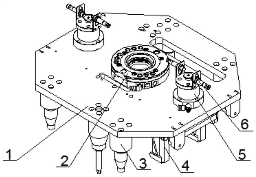
[0042] Please see attached figure 1 , the present invention provides a workpiece clamping device for a robot deburring workstation, comprising a fixed plate 1, on which a positioning mechanism 3, a floating pressing mechanism 4 for floating and pressing the workpiece, and A locking mechanism 5 that maintains reliability and a feedback mechanism 6 that can be electrically connected to an external control system.

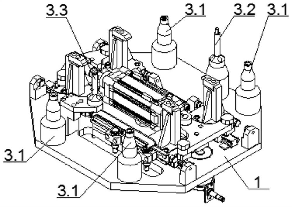
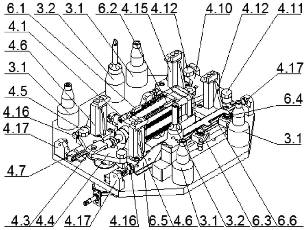
[0043] Please see attached figure 2 , the positioning mechanism 3 includes a first positioning member 3.1, a second positioning member 3.2 and a third positioning member 3.3. T...


PUM


Abstract

The invention provides a workpiece clamping device for a robot deburring workstation, which includes a fixed plate, and a floating pressing mechanism is arranged on one side of the fixing plate; the floating pressing mechanism includes a front floating plate, a front pressing head, a rear floating plate, a rear pressing Tight head and linear drive part; the linear drive part is floatingly arranged on the fixed plate, and the front floating plate and the rear floating plate are connected to both ends of the linear drive part respectively; Tightening head, the rear floating plate is located on both sides of the fixed plate in the direction of the center line, and the rear pressing head is respectively movable; the front pressing head and the rear pressing head are both slidingly connected with the fixing plate, and the sliding movement of the front pressing head and the rear pressing head The direction is parallel to the midline of the fixed plate. This application adopts the method of floating compression to compress the workpiece, which improves the contact effect between each compression point and the workpiece, ensures that the workpiece is accurately positioned and compressed, improves the compression effect of the workpiece, and cooperates with the two major mechanisms of locking and feedback to improve the pressure. Tight precision and enabling motion feedback.

Description

technical field [0001] The invention relates to the technical field of automobile parts processing, in particular to a workpiece clamping device for a robot deburring workstation. Background technique [0002] With the continuous development of the automotive industry, the competitive fixtures in the automotive industry have higher and higher requirements for the processing quality of auto parts. [0003] After the machine tool machining parts are completed, there will be a large number of burrs at the intersection of the machined surface and the non-machined surface, or the intersection of two machining features; the existence of burrs will bring hidden safety and functional hazards, so it is necessary to remove the burrs, For workpieces with complex shapes and many internal holes, the burrs are generally removed by hand, and the manual deburring method not only has a harsh working environment, but also has a high work intensity. Therefore, using robot deburring instead of ...

Claims


Application Information

Patent Timeline
Patent Type & Authority Patents(China)
IPC IPC(8): B23Q3/08
CPCB23Q3/08
Inventor 卢红印秦瑶仙
Owner WUXI BEST PRECISION MACHINERY
Learn More