Rotary transmission device and method
一种传动装置、回转装置的技术,应用在传动装置、摩擦传动装置、传动装置零件等方向,能够解决传动效率低、整机耐冲击性和刚性差、精度差等问题,达到降低布置数量、降低移动阻力、提高传动效率的效果
- Summary
- Abstract
- Description
- Claims
- Application Information
AI Technical Summary
Problems solved by technology
Method used
Image

Examples
Embodiment 1
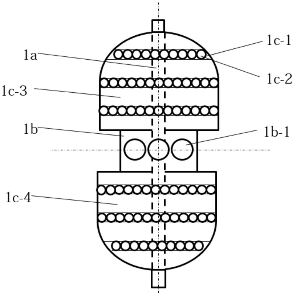
[0052] This embodiment provides a slewing device 1 that can be used as a main part of an intermediate transmission in a multi-stage transmission.
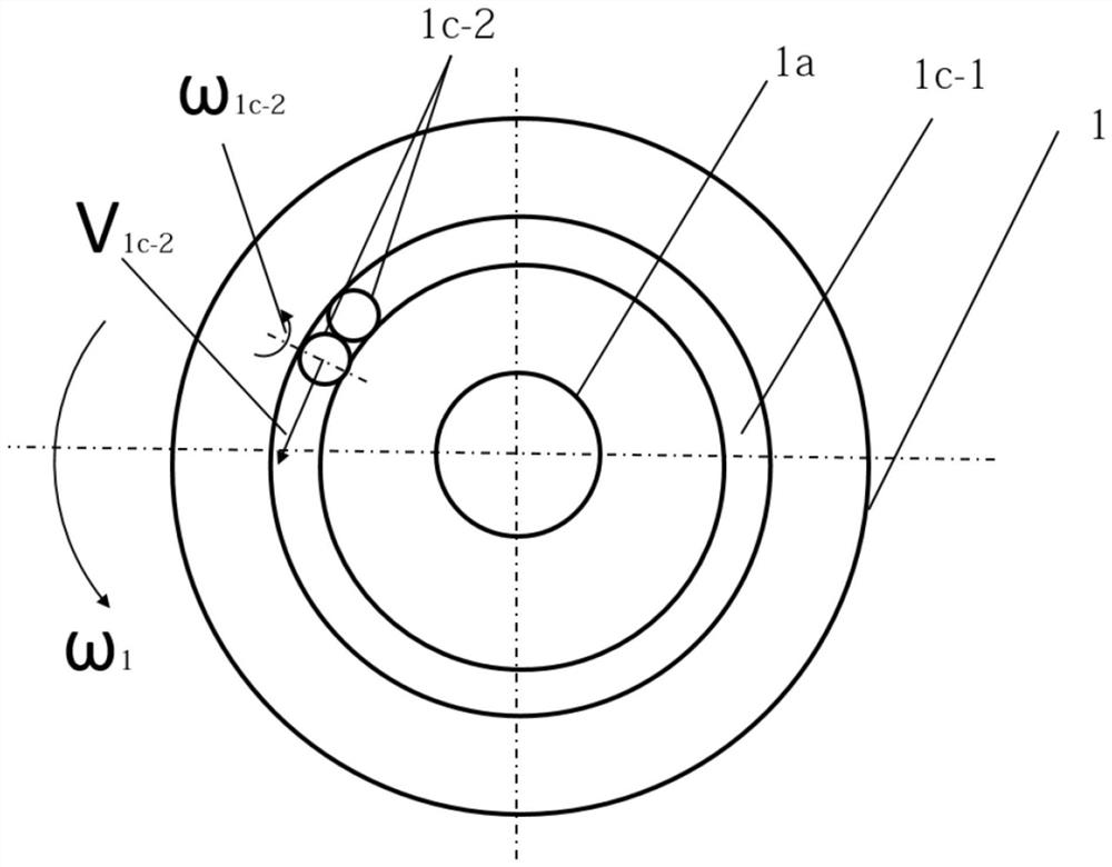
[0053] like figure 2 As shown, the swivel device 1 includes a base body 1c. End-to-end raceways 1c-1 are arranged on the base body 1c. The raceway 1c-1 is used to accommodate several first rollers 1c-2. Preferably, the first rolling element 1c-2 is a rolling part formed by rotation, which can revolve around the axis of the base body 1c on the raceway 1c-1 in a manner of self-rotation on its own axis. For example, the first roller 1c-2 may be a sphere, an ellipsoid, a cylinder or a cone. Adjacent two first rollers 1c-2 are in partial contact with each other. The first roller 1c-2 is also in partial contact with the raceway 1c-1. In the case where two adjacent first rollers 1c-2 are in partial contact with each other, several rollers 1c-2 fill the raceway 1c-1 in such a way that the raceways 1c-1 are in partial contact with eac...
Embodiment 2
[0060] This embodiment may be a further improvement and / or supplement to Embodiment 1, and repeated content will not be repeated here. In the case of no conflict or contradiction, the whole and / or part of the content of the preferred implementations of other embodiments may serve as supplements to this embodiment.
[0061] Preferably, the axis of the rotary device 1 and the axis of the first transmission turntable 1b can be set in such a way that they do not coincide with each other but are in the same direction. Due to the eccentric setting of the first transmission turntable 1b, when the slewing device 1 rotates around its own axis, the first transmission turntable 1b rotates eccentrically around the axis of the slewing device 1, so that the rolling hole 1b-1 on the first transmission turntable 1b The dynamic friction pair is formed in discontinuous contact with the second roller 3 b - 3 on the first transmission member 3 , so that the first transmission member 3 rotates int...
Embodiment 3
[0063] This embodiment may be a further improvement and / or supplement to Embodiment 1, and repeated content will not be repeated here. In the case of no conflict or contradiction, the whole and / or part of the content of the preferred implementations of other embodiments may serve as supplements to this embodiment. This embodiment discloses a transmission device.
[0064] Preferably, the transmission device includes a slewing device 1 and a second transmission member 2 to realize one-stage transmission.
[0065] Or, preferably, the transmission device includes a slewing device 1 and a first transmission member 3 to realize a first-stage transmission.
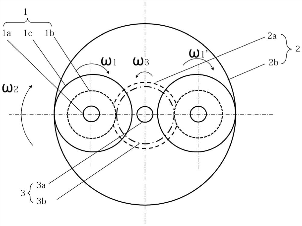
[0066] Or, preferably, the transmission device includes a slewing device 1 , a first transmission member 3 and a second transmission member 2 to realize two-stage transmission. Its specific operation diagram is as follows figure 1 shown. The external power drives the second transmission part 2 as the active part with ω 2 Rot...
PUM
 Abstract
Description
Claims
Application Information
 - R&D
- Intellectual Property
- Life Sciences
- Materials
- Tech Scout
- Unparalleled Data Quality
- Higher Quality Content
- 60% Fewer Hallucinations
Browse by: Latest US Patents, China's latest patents, Technical Efficacy Thesaurus, Application Domain, Technology Topic, Popular Technical Reports.
© 2025 PatSnap. All rights reserved.Legal|Privacy policy|Modern Slavery Act Transparency Statement|Sitemap|About US| Contact US: help@patsnap.com