
A control method for a building heat exchange unit with a molten salt energy storage heating system

A heat exchange unit and heating system technology, applied to heating systems and central heating, can solve the problems of insufficient hydraulic control, high heat density, uneven distribution of heat sources, etc., to facilitate installation and later maintenance, reduce pipe diameter and The effect of occupying land and saving construction investment

Active Publication Date: 2022-06-03
浙江英集动力科技有限公司
View PDF6 Cites 0 Cited by
  • Summary
  • Abstract
  • Description
  • Claims
  • Application Information

AI Technical Summary

Problems solved by technology

However, the scope of the primary network will be enlarged due to the introduction of the primary network pipes to the front of the building, and due to the uneven distribution of heat sources or insufficient hydraulic regulation, some primary heating pipe networks at the remote end cannot provide sufficient heat for the building. To solve this problem, the primary network adjustment needs to increase the load of the entire heating system. On the one hand, it will cause waste of heat energy. On the other hand, the primary network adjustment has a large lag, and it is difficult to solve the problem of insufficient heating for these users in a timely and accurate manner.
[0003] In the prior art, there are auxiliary heat sources used in the secondary network to cope with extreme weather conditions; for example, "building heat exchange unit heating system (CN206831644U)", in which the thermal energy generated by the auxiliary heat source often exceeds the building heat exchange The required heat energy is likely to cause waste of electric energy during long-term use; the second is that its solution can only be used for peak regulation in extreme weather, and cannot be used when the heat source fails and the load is reduced; the third is that its technology The auxiliary heat source uses water as the heat storage medium with high heat density, and the installation of the water storage tank occupies a large area

Method used


Image

  • A control method for a building heat exchange unit with a molten salt energy storage heating system
  • A control method for a building heat exchange unit with a molten salt energy storage heating system
  • A control method for a building heat exchange unit with a molten salt energy storage heating system

Examples


Embodiment Construction

[0040] The present invention will be described in detail below with reference to the accompanying drawings and specific embodiments, wherein the exemplary embodiments and descriptions are only used to explain the present invention, but are not intended to be improperly limited to the present invention.

[0041] It should be noted that the embodiments in the present application and the features of the embodiments may be combined with each other in the case of no conflict. The present invention will be described in detail below with reference to the accompanying drawings and in conjunction with the embodiments.

[0042] It should be noted that the terminology used herein is for the purpose of describing specific embodiments only, and is not intended to limit the exemplary embodiments according to the present application. As used herein, unless the context clearly dictates otherwise, the singular is intended to include the plural as well, furthermore, it is to be understood that ...


PUM


Abstract

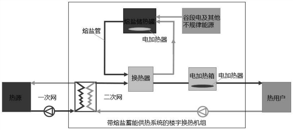
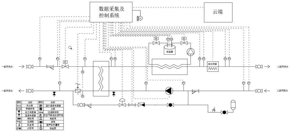
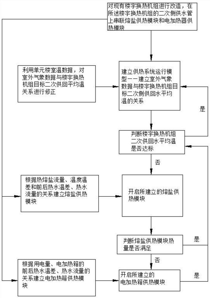
The invention discloses a control method for a building heat exchange unit with a molten salt energy storage heat supply system. Step S1 transforms the existing building heat exchange units, adding molten salt heat exchangers and electric heating boxes on the secondary side. Step S2 establishes the heat exchange unit heating system operation module for the heat exchange unit transformed in step S1; step S3 establishes a molten salt heating module; step S4 establishes an electric heating box heating module; step S5 establishes a heat supply module for step S2 The system operation analysis model establishes the operation analysis module of the heat exchange unit heating system. Determine the operation status according to the average temperature of the secondary supply and return water; choose to enter the molten salt heating module, and then choose to enter the electric heating box heating module according to the heat supply of the molten salt heating module; until the average temperature of the secondary supply and return meets the requirements, according to Step S2 runs. This patent is based on a multi-energy complementary and synergistic strategy, with the help of the industrial Internet, cloud regulation, and the use of molten salt heating modules to achieve precise and rapid heating of buildings; realizing end-point precise heating and on-demand heating.

Description

technical field [0001] The invention relates to a heating system, in particular to a control method of a building heat exchange unit with a molten salt energy storage heating system. Background technique [0002] The building heat exchange mode can use a building or a building with the same thermal characteristics as a heating unit, lead the primary network pipeline to the front of the building, and connect it to the building heat exchange unit (station), which can not only reduce the heating radius, but also reduce the energy consumption. The hysteresis of the secondary network realizes the decoupling of the inter-building regulation and the in-building regulation, making the regulation more flexible and precise, and reducing the cost of laying the heating pipe network. However, since the primary network pipeline is led to the front of the building, the scope of the primary network will be enlarged, and due to uneven distribution of heat sources or insufficient hydraulic co...

Claims


Application Information

Patent Timeline
Patent Type & Authority Patents(China)
IPC IPC(8): F24D11/00F24D19/10
CPCF24D11/004F24D19/1009F24D2200/08Y02P80/20
Inventor 杨靖时伟周孝明谢金芳
Owner 浙江英集动力科技有限公司
Learn More