Packaging tube shell for surface-mounted sensor and surface-mounted sensor using same

A technology for packaging tubes and sensors, which is applied in the direction of electric solid-state devices, semiconductor devices, electric radiation detectors, etc., can solve the problems of complex manufacturing process, low production efficiency, and many manpower, so as to reduce production costs, improve production efficiency, and facilitate The effect of production assembly

Pending Publication Date: 2021-07-09
瓷金科技(河南)有限公司
View PDF6 Cites 2 Cited by
  • Summary
  • Abstract
  • Description
  • Claims
  • Application Information

AI Technical Summary

Problems solved by technology

[0003] The substrate of the above-mentioned chip type pyroelectric infrared sensor is equivalent to forming a package shell. The substrate is a metallized ceramic substrate or an epoxy resin PCB board. After the substrate is formed, a metal layer needs to be fixed on the surface and the inner side, and the manufacturing process is complicated.
In addition, in the production and assembly process of components, it is necessary to fix the support in the packaging shell before installing the infrared sensitive element, and it is necessary to electrically connect the infrared sensitive element to the signal processing circuit. This process is complicated and cumbersome, causing production The efficiency is relatively low, and more manpower is required, which increases the production cost

Method used


Image

  • Packaging tube shell for surface-mounted sensor and surface-mounted sensor using same
  • Packaging tube shell for surface-mounted sensor and surface-mounted sensor using same
  • Packaging tube shell for surface-mounted sensor and surface-mounted sensor using same

Examples


Embodiment Construction

[0050] In order to make the object, technical solution and advantages of the present invention clearer, the present invention will be further described in detail below in conjunction with the accompanying drawings and embodiments. It should be understood that the specific embodiments described here are only used to explain the present invention, and are not intended to limit the present invention, that is, the described embodiments are only some of the embodiments of the present invention, but not all of the embodiments. The components of the embodiments of the invention generally described and illustrated in the figures herein may be arranged and designed in a variety of different configurations.

[0051] Accordingly, the following detailed description of the embodiments of the invention provided in the accompanying drawings is not intended to limit the scope of the claimed invention, but merely represents selected embodiments of the invention. Based on the embodiments of the...


PUM


Abstract

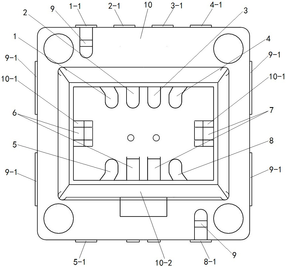
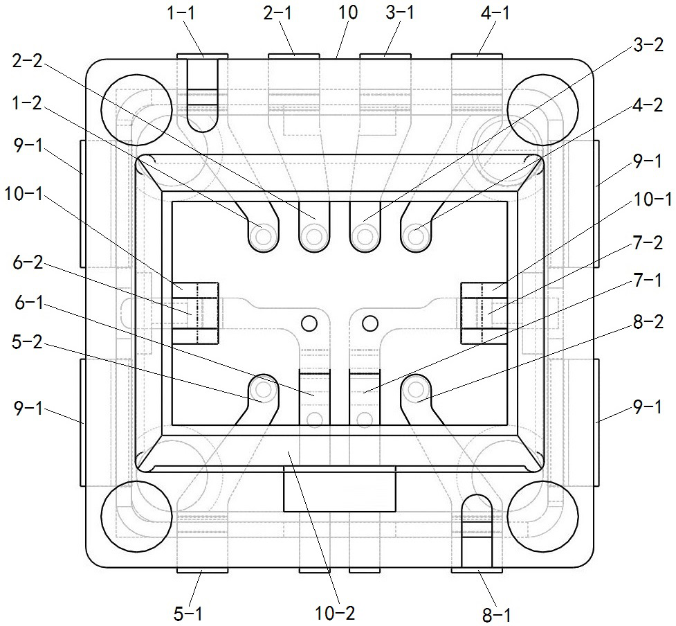
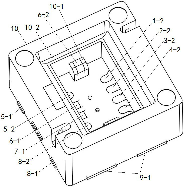
The invention provides a packaging tube shell for a surface-mounted sensor and the surface-mounted sensor using the same, wherein the packaging tube shell comprises a plastic main body, a metal shielding cover, a first conductive lead and a second conductive lead; the plastic main body is provided with a supporting body through integral injection molding; the metal shielding cover is fixed in the plastic main body through injection molding; the first conductive lead is fixed on the plastic main body through injection molding and comprises a first end exposed out of the outer side wall of the plastic main body and a second end exposed out of the bottom surface of the accommodating chamber; and the second conductive lead is fixed on the plastic main body through injection molding, is not exposed out of the outer side wall of the plastic main body, and comprises a first exposed part exposed out of the bottom surface of the accommodating chamber and a second exposed part exposed out of the support body. In the production and assembly process, the step of independently installing the supporting body, the shielding cover and the second conductive lead is omitted, the manufacturing process of the tube shell is simplified, the production and assembly process is simplified, manpower can be saved, efficiency is improved, and cost is reduced. And meanwhile, the second conductive lead does not form a soldering tin pin, so that a good shielding effect is ensured, and the sensor is prevented from being out of order due to external interference.

Description

technical field [0001] The invention relates to the technical field of sensor product packaging, in particular to a packaging shell for a patch sensor and a patch sensor using the shell. Background technique [0002] Pyroelectric infrared sensor is a kind of heat sensitive sensor, which converts the heat signal sent by people or animals through the infrared sensitive element into electrical signal through the signal processing circuit. For example, a chip-type pyroelectric infrared sensor disclosed in the Chinese invention patent application with the application publication number of CN108469305A includes a closed shell composed of a cover plate and a base plate, and an infrared sensitive element and a support for fixing the infrared sensitive element are contained in the closed shell. And a signal processing circuit; wherein, the cover plate is an infrared optical filter; the frame surface and the inner side of the substrate are provided with a metal layer forming an electr...

Claims


Application Information

Patent Timeline
Patent Type & Authority Applications(China)
IPC IPC(8): G01J5/34H01L23/043H01L23/10H01L23/49H01L23/552
CPCG01J5/34H01L23/043H01L23/10H01L23/49H01L23/552
Inventor 刘永良刘奇禹贵星马世远
Owner 瓷金科技(河南)有限公司
Why Eureka
Try Eureka