
Low-profile double-frequency common-caliber monopole antenna based on cross-layer folding structure
A folded structure, monopole antenna technology, applied in resonant antenna, radiating element structure, slender active unit end feed, etc., can solve the problems of increased volume, insufficient bandwidth, and high thickness. Achieve the effect of reducing the volume and weight of the antenna, reducing the thickness, and ensuring the quality of reception
- Summary
- Abstract
- Description
- Claims
- Application Information
AI Technical Summary
Problems solved by technology
Method used
Image


Examples
Embodiment 1
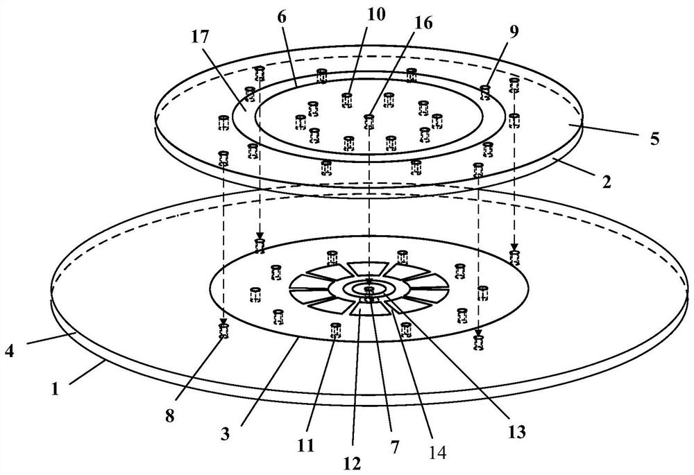
[0059] In this embodiment, low-profile dual-frequency co-aperture monopole antennas with center frequencies of 2.4 GHz and 5.5 GHz are designed and manufactured.
[0060] In this embodiment, the dielectric constant ε of the upper dielectric substrate 2 and the lower dielectric substrate 4 r Both are 2.2, and the thickness H is 1.57mm.
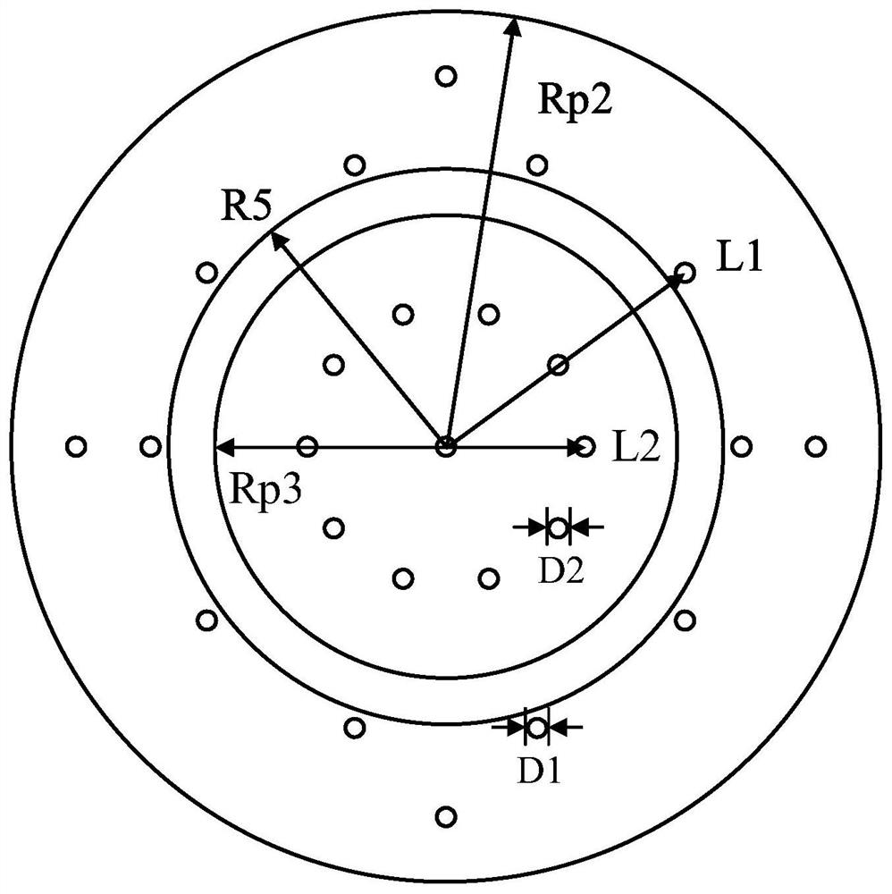
[0061] In this embodiment, the radius Rp3 of the first circular patch 6 = 26mm; the inner radius R5 of the annular patch 5 = 29mm, the outer radius Rp2 = 47mm; the diameter D1 of the first metallized via hole 9 = 0.7mm, The number N1 = 20, the distance L1 from the center of the circle = 32 mm; the straight length D2 of the second metallized via hole 10 = 0.65 mm, the number N2 = 14, and the distance L2 from the center of the circle = 20.5 mm.
[0062] In this embodiment, the radius Rp1 of the second circular patch 3=35mm; the radius Rg=80mm of the metal floor 1; the straight longitude D3=0.8mm of the third metallized via hole 11, the number N3...
Embodiment 2
[0068] In this embodiment, low-profile dual-frequency co-aperture monopole antennas with center frequencies of 2.35 GHz and 5 GHz are designed.
[0069] In this embodiment, the dielectric constant ε of the upper dielectric substrate 2 and the lower dielectric substrate 4 r Both are 2.2, and the thickness H is 1.57mm.
[0070] In this embodiment, the radius Rp3 of the first circular patch 6 = 28 mm; the inner radius R5 of the annular patch 5 = 28.7 mm, and the outer radius Rp2 = 46 mm; the straight line D1 of the first metallized via hole 9 = 0.7 mm , the number N1 = 20, the distance L1 from the center of the circle = 29.4 mm; the straight line D2 of the second metallized via 10 = 0.8 mm, the number N2 = 14, and the distance L2 from the center of the circle = 22.5 mm.
[0071] In this embodiment, the radius Rp1 of the second circular patch 3=35mm; the radius Rg=80mm of the metal floor 1; the straight longitude D3=0.8mm of the third metallized via hole 11, the number N3=20, and...
PUM
| Property | Measurement | Unit |
|---|---|---|
| radius | aaaaa | aaaaa |
Abstract
Description
Claims
Application Information