Eureka AIR delivers breakthrough ideas for toughest innovation challenges, trusted by R&D personnel around the world.

Machining method of high-precision sealing hole

A processing method and technology for sealing holes, which are applied in metal processing equipment, metal processing mechanical parts, manufacturing tools, etc., can solve the problems of single rough sealing hole processing method, unable to seal hole size processing, and difficult to meet the needs of use, etc., to prevent The effect of dust and debris affecting the processing environment, improving processing adjustability, and improving processing adaptability

Active Publication Date: 2021-07-13
南通德元机械制造有限公司
View PDF4 Cites 0 Cited by
  • Summary
  • Abstract
  • Description
  • Claims
  • Application Information

AI Technical Summary

Problems solved by technology

[0002] The three-way valve is suitable for automobiles, instrumentation and other industries. It is used to control the flow direction of the medium in the pipeline. The pneumatic three-way valve is remade from an ordinary three-way ball valve. The valve body at the outlet, the valve core with a through hole and rotatable in the valve body, the valve stem fixedly connected with the valve core, the gear fixedly connected with the valve stem, the rack meshed with the gear, and the When the three-way ball valve is in the normal position, the sealing hole of the valve core is connected with the inlet and an outlet of the valve body, and when the flow direction of the medium in the pipeline needs to be switched, the rack is driven by the cylinder. The drive gear rotates at a certain angle, thereby driving the rotation of the valve stem fixedly connected with the gear, and then making the valve core fixedly connected with the valve stem rotate at a certain angle to close the original outlet and make the valve core seal the hole It becomes connected with the inlet of the valve body and another outlet. However, the existing sealing hole processing method is single and rough, which is difficult to meet the needs of use, and different sealing hole sizes cannot be processed on the same processing line, and the processing efficiency is low.

Method used


Image

  • Machining method of high-precision sealing hole

Examples


Embodiment Construction

[0024] The implementation mode of the present invention is illustrated by specific specific examples below, and those who are familiar with this technology can easily understand other advantages and effects of the present invention from the contents disclosed in this description. Obviously, the described embodiments are a part of the present invention. , but not all examples. Based on the embodiments of the present invention, all other embodiments obtained by persons of ordinary skill in the art without making creative efforts belong to the protection scope of the present invention.

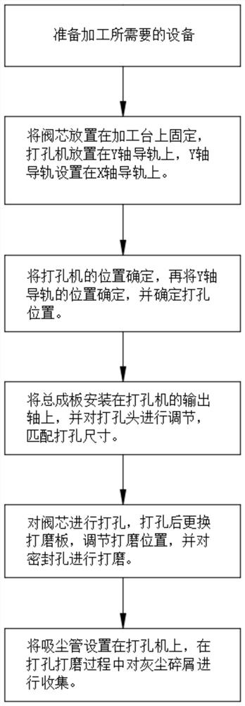
[0025] refer to figure 1 , a processing method for a high-precision sealing hole, the method comprising:

[0026] S1: Place the spool on the processing table, use the fixture to fix the position of the spool, erect the punching machine on the Y-axis guide rail, and lay the Y-axis guide rail on the X-axis guide rail to realize the punching machine. Position adjustment, and set screw knob 1 on th...


PUM


Abstract

The invention belongs to the field of valve machining, particularly relates to a machining method of a high-precision sealing hole. The following scheme is now put forward aiming at the problems that an existing sealing hole machining method is single and rough, the use requirement is difficult to meet, sealing holes with different sizes cannot be machined on the same machining line, and the machining efficiency is low. The method comprises the steps that S1, a valve element is placed on a machining table, a clamp is used for fixing the position of the valve element, a perforating machine is erected on a Y-axis guide rail, the Y-axis guide rail is laid on an X-axis guide rail, and position adjustment of the perforating machine can be achieved. According to the sealing hole machining method, different use requirements can be met, sealing holes of different sizes can be machined on the same machining line, the machining efficiency is high, dust and impurities can be restrained and collected in the punching and grinding process, and the situation that the machining environment is affected by dust and chippings in the machining process is effectively prevented.

Description

technical field [0001] The invention relates to the technical field of valve processing, in particular to a processing method for a high-precision sealing hole. Background technique [0002] The three-way valve is suitable for automobiles, instrumentation and other industries. It is used to control the flow direction of the medium in the pipeline. The pneumatic three-way valve is remade from an ordinary three-way ball valve. The valve body at the outlet, the valve core with a through hole and rotatable in the valve body, the valve stem fixedly connected with the valve core, the gear fixedly connected with the valve stem, the rack meshed with the gear, and the When the three-way ball valve is in the normal position, the sealing hole of the valve core is connected with the inlet and an outlet of the valve body, and when the flow direction of the medium in the pipeline needs to be switched, the rack is driven by the cylinder. The drive gear rotates at a certain angle, thereby ...

Claims


Application Information

Patent Timeline
Patent Type & Authority Applications(China)
IPC IPC(8): B23P23/04B23Q1/62B23Q11/00B23B41/00B23B47/30B24B19/00B24B55/06
CPCB23P23/04B23Q1/621B23Q11/0046B23B41/00B23B47/30B24B19/00B24B55/06
Inventor 潘海涌何小蓉江正彬於智勇
Owner 南通德元机械制造有限公司
Why Eureka
Eureka Blog
Learn More