Crankshaft and engine

A crankshaft and main shaft technology, applied in the engine field, can solve the problems of reducing the strength of the crankshaft, reducing the displacement of the engine, increasing the resistance of the crankshaft, etc.

Pending Publication Date: 2021-07-13
青岛德盛机械制造有限公司
View PDF0 Cites 0 Cited by
  • Summary
  • Abstract
  • Description
  • Claims
  • Application Information

AI Technical Summary

Problems solved by technology

[0004] At present, there are mainly three ways to reduce the weight of the crankshaft: 1. Change the structure of the crankshaft shape, which will affect the running state of the crankshaft in the engine; 2. Reduce the crankshaft shape size, which reduces the engine displacement; 3. Part of the material of the crankshaft is removed, which reduces the strength of the crankshaft and increases the resistance of the crankshaft during operation, affecting its service life

Method used


Image

  • Crankshaft and engine
  • Crankshaft and engine
  • Crankshaft and engine

Examples


Embodiment Construction

[0035] The following will clearly and completely describe the technical solutions in the embodiments of the present invention with reference to the accompanying drawings in the embodiments of the present invention. Obviously, the described embodiments are only some, not all, embodiments of the present invention. Based on the embodiments of the present invention, all other embodiments obtained by persons of ordinary skill in the art without making creative efforts belong to the protection scope of the present invention.

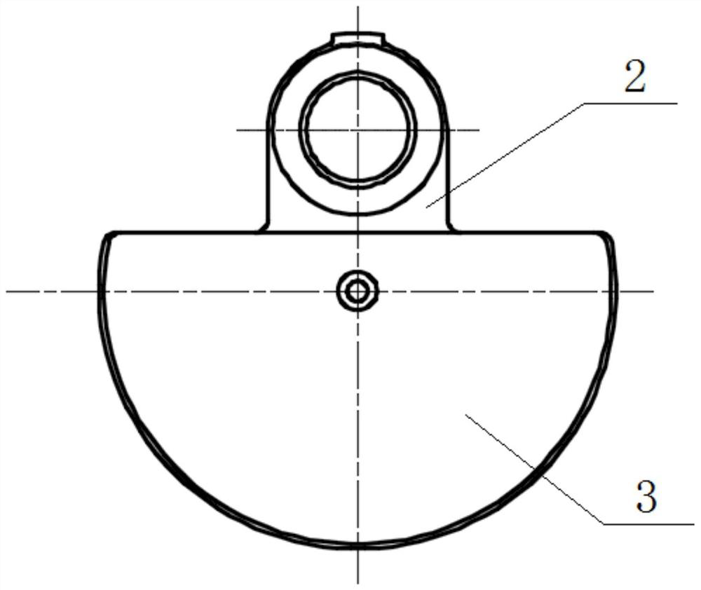
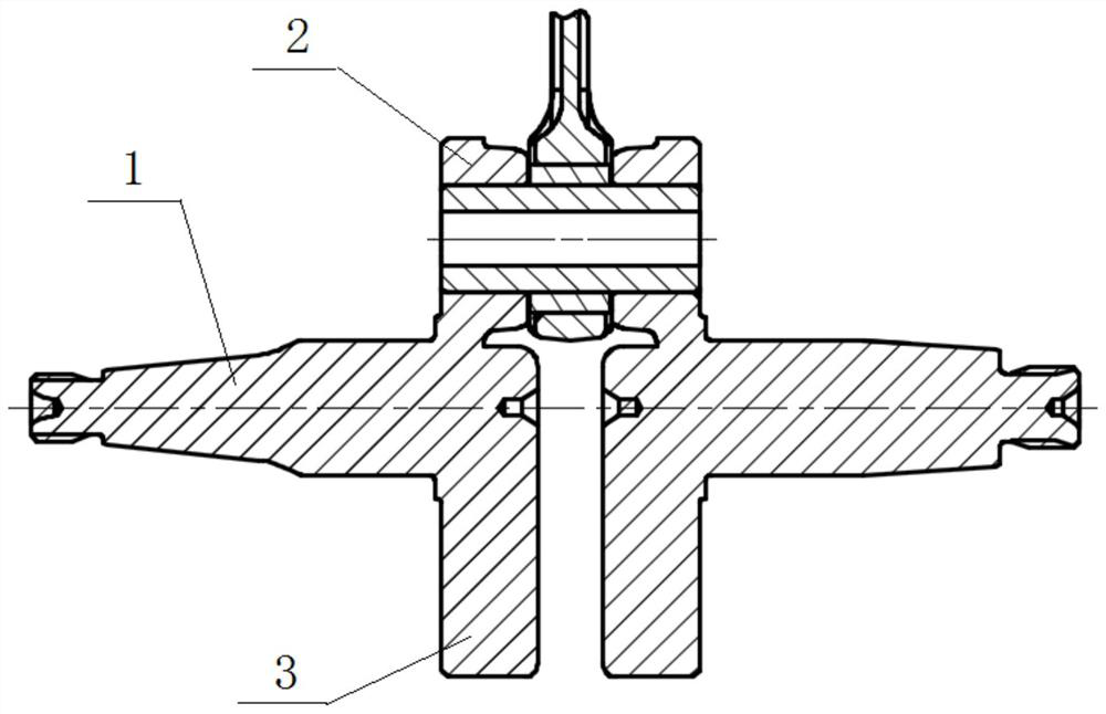
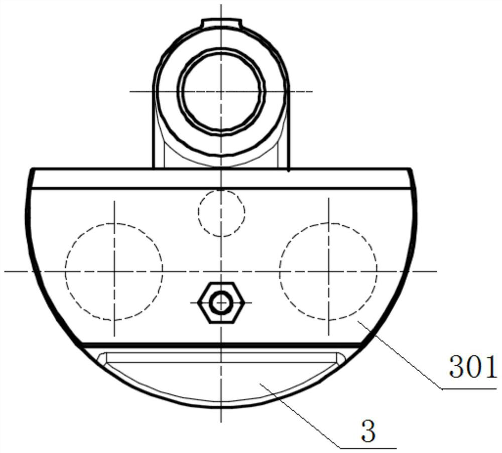
[0036] Please refer to Figure 1 to Figure 8 , figure 1 Side view when no counterweight hole is set for the crankshaft; figure 2 A sectional view of the crankshaft without a counterweight hole. image 3 A side view of a crankshaft provided by an embodiment of the present invention; Figure 4 A sectional view of a crankshaft provided by an embodiment of the present invention; Figure 5 It is a schematic diagram of the structure of the counterweight; Imag...


PUM


Abstract

The invention discloses a crankshaft and an engine. The crankshaft comprises a main shaft, a crank and a balance block, balance weight holes are formed in the balance block and connected with balance weight blocks, and the weight of the balance weight blocks is less than that of the same volume part formed on the balance weight blocks, so that the weight reduction effect is achieved, and the purposes of energy conservation and emission reduction are achieved; and the current state of an original crankshaft can also be guaranteed, and the displacement is not changed, so that the crankshaft after weight reduction can achieve power output of the original crankshaft in the operation process.

Description

technical field [0001] The invention relates to the technical field of engines, in particular to a crankshaft, and also to an engine comprising the crankshaft. Background technique [0002] With the emphasis on environmental protection, how to save energy and reduce emissions is a problem that people need to solve. For the engine, reducing its curb weight is one of the most important and direct ways to save energy and reduce emissions. [0003] Among them, the crankshaft is the core component of the engine. Its function is to convert the power from the piston and connecting rod into torque, and convert the linear motion of the piston into rotary motion to drive the transmission system, valve train and other auxiliary components. device. The crankshaft material is usually high-quality alloy steel, and its weight usually accounts for 10% to 20% of the total weight of the engine. On the premise of ensuring the strength and safety of the engine, reducing the weight of the cra...

Claims


Application Information

Patent Timeline
Patent Type & Authority Applications(China)
IPC IPC(8): F16C3/20F16F15/28
CPCF16C3/20F16F15/283
Inventor 尚丹鸽王涛远毛建建
Owner 青岛德盛机械制造有限公司
Why Eureka
Try Eureka