
Feature determination method and device, electronic equipment and storage medium

A technology for determining methods and feature information, applied in image data processing, microscopy, optics, etc., can solve problems such as inability to disperse data, fitting, and difficult to deal with astigmatism changes, and achieve the effect of reducing memory resources

Active Publication Date: 2021-07-13
山东迈科显微生物科技有限公司
View PDF8 Cites 0 Cited by
  • Summary
  • Abstract
  • Description
  • Claims
  • Application Information

AI Technical Summary

Problems solved by technology

[0004]The existing Gaussian fitting method has a fixed fitting model and cannot fit pixels with high-order aberrations, and for region-specific phase differences say, each region has a specific aberration
The other uses the cubic spline interpolation method, by fitting the image to a function with the largest cubic power, and because of this cubic spline interpolation method, there are certain shortcomings: first, due to the continuity of the cubic function, it cannot Scattered data fitting, dealing with scatter data also requires translation of the measured interpolated data to the voxel grid
Second, because the cubic spline fitting method has coefficients to be calculated for each order of each interpolation point, when the number of interpolations needs to be improved to improve the fitting quality, the number of calculation coefficients will also increase, and the amount of calculation is Increase exponentially. For example, for a 14*14 pixel area, 196*33 spline coefficients need to be calculated, which is 5292 matrix operations, and the number of imaging on the z-axis is 500. In computing, the processor undoubtedly bears a huge burden
Third, the cubic spline fitting can only fit the three-dimensional information of the image at present, and it is difficult to realize the higher-dimensional information due to the limitation of memory. Handle astigmatism changes due to distance between fluorescent molecules and glass slides

Method used


Image

  • Feature determination method and device, electronic equipment and storage medium
  • Feature determination method and device, electronic equipment and storage medium
  • Feature determination method and device, electronic equipment and storage medium

Examples


Embodiment 1

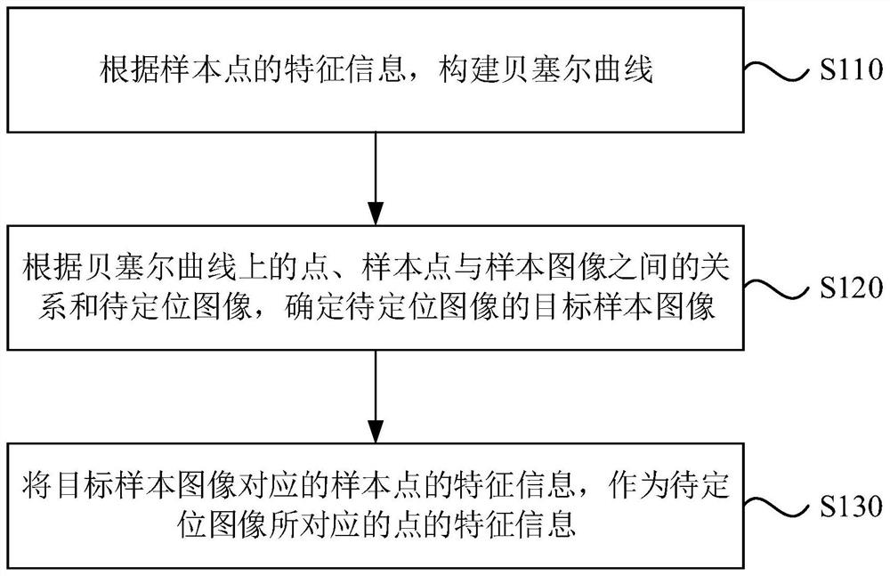
[0027] Figure 1A It is a flow chart of a feature determination method provided by Embodiment 1 of the present invention. This embodiment is applicable to the situation of single-molecule image positioning. The method can be executed by a feature determination device, which can be implemented by software / hardware, and can be Integrated in an electronic device carrying a feature determination function, such as a server.

[0028] Such as Figure 1A As shown, the method may specifically include:

[0029] S110. Construct a Bezier curve according to the feature information of the sample points.

[0030] In this embodiment, the fluorescent bead is used as a template, the fluorescent bead is placed on the microscope, and its three-dimensional position is moved by adjusting the Z-axis translation stage, and point diffusion images at different positions are obtained as sample images. Optionally, in this embodiment, the fluorescent beads at different positions are used as sample points...

Embodiment 2

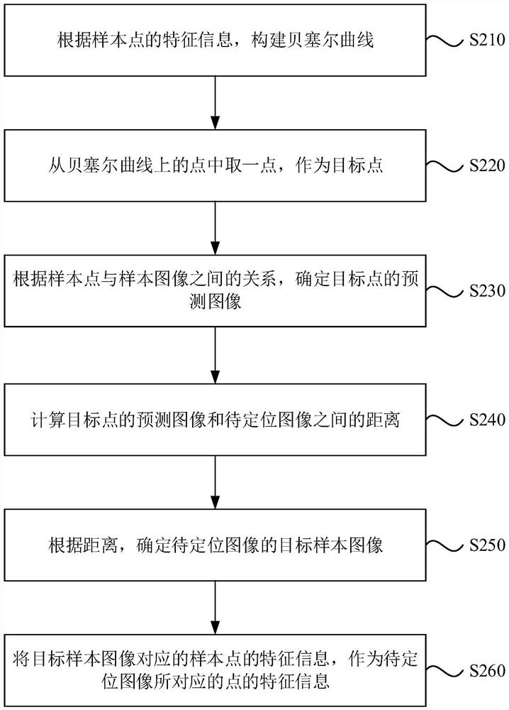
[0048] figure 2 It is a flow chart of a feature determination method provided by Embodiment 2 of the present invention. On the basis of the above embodiments, "according to the relationship between the points on the Bezier curve, the sample point and the sample image, and the image to be positioned, Determine the target sample image of the image to be positioned" for optimization, providing an optional implementation solution.

[0049] Such as figure 2 As shown, the method may specifically include:

[0050] S210. Construct a Bezier curve according to the feature information of the sample points.

[0051] S220. Take one point from the points on the Bezier curve as the target point.

[0052] In this embodiment, a point is randomly selected from the points on the Bezier curve as the target point.

[0053] S230. Determine a predicted image of the target point according to the relationship between the sample point and the sample image.

[0054] In this embodiment, an image p...

Embodiment 3

[0068] image 3 It is a schematic structural diagram of a feature determination device provided in Embodiment 3 of the present invention. This embodiment is applicable to single-molecule image positioning. The device can be realized by software / hardware, and can be integrated into an electronic device carrying a feature determination function , for example in the server.

[0069] Such as image 3 As shown, the device may include a curve construction module 310, a target sample image determination module 320 and a feature information determination module 330, wherein,

[0070] A curve construction module 310, configured to construct a Bezier curve according to the feature information of the sample points;

[0071] The target sample image determination module 320 is used to determine the target sample image of the image to be positioned according to the relationship between the point on the Bezier curve, the sample point and the sample image, and the image to be positioned;

...


PUM


Abstract

The invention discloses a feature determination method and device, electronic equipment and a storage medium, and belongs to the technical field of single molecule positioning imaging. The method comprises the following steps: constructing a Bezier curve according to feature information of sample points; determining a target sample image of the to-be-positioned image according to the point on the Bezier curve, the relationship between the sample point and the sample image and the to-be-positioned image; and taking the feature information of the sample points corresponding to the target sample image as the feature information of the points corresponding to the to-be-positioned image. According to the technical scheme, compared with an existing Gaussian fitting and cubic spline interpolation method, more imaging information is obtained, meanwhile, memory resources are reduced, and a new thought is provided for multi-dimensional single-molecule positioning imaging.

Description

technical field [0001] Embodiments of the present invention relate to single-molecule localization imaging technology, and in particular to a feature determination method, device, electronic equipment, and storage medium. Background technique [0002] With the advancement of optical equipment and technology, the practical application of microscopes has reached the theoretical resolution limit. Due to the influence of optical diffraction, image points will appear blurred on the imaging surface of the optical system. The degree of blurring is related to the wavelength of light and the aperture value. In order to overcome the diffraction limit, a variety of super-resolution microscopy imaging methods have been proposed, including stochastic optical reconstruction microscopy (STORM) and photoactivated localization microscopy (PALM). Realize the imaging of individual fluorescent molecules, and finally obtain the three-dimensional position of each molecule. [0003] Among the exi...

Claims


Application Information

Patent Timeline
IPC IPC(8): G06T3/40G02B21/00G02B21/36
CPCG06T3/4007G02B21/365G02B21/0004G02B21/008G02B21/0076
Inventor 李依明李孟帆
Owner 山东迈科显微生物科技有限公司
Learn More