Forming method of semiconductor structure

A technology of semiconductors and conductors, applied in the field of isolation structures and their formation

Inactive Publication Date: 2021-07-13
TAIWAN SEMICON MFG CO LTD
View PDF0 Cites 0 Cited by
  • Summary
  • Abstract
  • Description
  • Claims
  • Application Information

AI Technical Summary

Problems solved by technology

In another example, the process of forming source / drain recesses may cause depth variations in the final epitaxial source / drain structures, negatively causing leakage currents

Method used


Image

  • Forming method of semiconductor structure
  • Forming method of semiconductor structure
  • Forming method of semiconductor structure

Examples


Embodiment Construction

[0056] The following detailed description can be accompanied by accompanying drawings to facilitate understanding of various aspects of the present invention. It is worth noting that various structures are used for illustration purposes only and are not drawn to scale, as is the norm in the industry. In fact, the dimensions of the various structures may be arbitrarily increased or decreased for clarity of illustration.

[0057] Different embodiments or examples provided in the following content can implement different structures of the embodiments of the present invention. The examples of specific components and arrangements are used to simplify the disclosure and not to limit the invention. For example, the statement that the first component is formed on the second component includes that the two are in direct contact, or there are other additional components interposed between the two instead of direct contact. In addition, spatial relative terms such as "below", "below", ...


PUM

PropertyMeasurementUnit
thicknessaaaaaaaaaa

Abstract

The invention relates to a forming method of a semiconductor structure. The semiconductor structure comprises a semiconductor substrate; an oxide layer on the semiconductor substrate; a high-dielectric-constant gate dielectric layer and a metal gate structure, which are staggered with the stack of the semiconductor layers; and an epitaxial source/drain structure adjacent to the high-dielectric-constant gate dielectric layer and the metal gate structure, wherein the oxide layer defines a bottom of the epitaxial source/drain structure.

Description

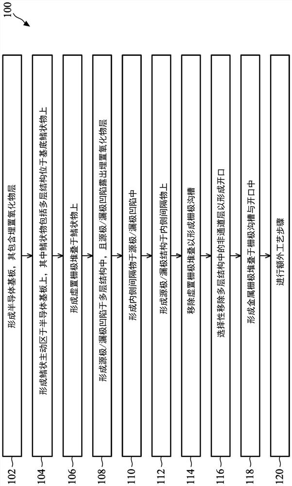
technical field [0001] Embodiments of the present invention relate to an isolation structure and its forming method, which are configured to block or eliminate the leakage current generated by the epitaxial source / drain structure in the all-around gate field effect transistor. Background technique [0002] The semiconductor industry has experienced rapid growth. Technological advances in semiconductor materials and design have resulted in each generation of semiconductor devices having smaller and more complex circuits than the previous generation. In the evolution of integrated circuits, functional density (eg, the number of interconnect devices per unit chip area) generally increases as geometric dimensions (eg, the smallest component or circuit that can be produced by the fabrication process employed) shrink. A shrinking process is often beneficial for increased throughput and lower associated costs. However, these advances have also increased the complexity of handling...

Claims


Application Information

Patent Timeline
Patent Type & Authority Applications(China)
IPC IPC(8): H01L21/8234H01L27/088
CPCH01L21/823431H01L21/823481H01L27/0886H01L29/66545H01L29/775H01L29/7848H01L29/165H01L21/02164H01L21/02236H01L21/02255B82Y10/00H01L29/66439H01L29/0673H01L29/0847H01L29/78696H01L29/42392H01L21/02238H01L21/2253H01L21/26533H01L21/7624H01L29/6653H01L29/66553H01L29/66742H01L29/66787H01L29/78603
Inventor 吴旭升刘昌淼尚慧玲
Owner TAIWAN SEMICON MFG CO LTD
Why Eureka
Try Eureka