Switch control circuit based on pin multiplexing, switch power supply system and frequency control method
A switch control circuit and frequency control technology, applied in the electronic field, can solve the problems of complex structure, many pins of the switch control circuit, unable to monitor the change of the original current, etc., achieving a simple structure, a wide range of market applications, and a small size. Effect
- Summary
- Abstract
- Description
- Claims
- Application Information
AI Technical Summary
Problems solved by technology
Method used
Image

Examples
Embodiment 1
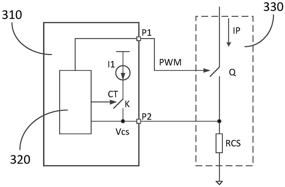
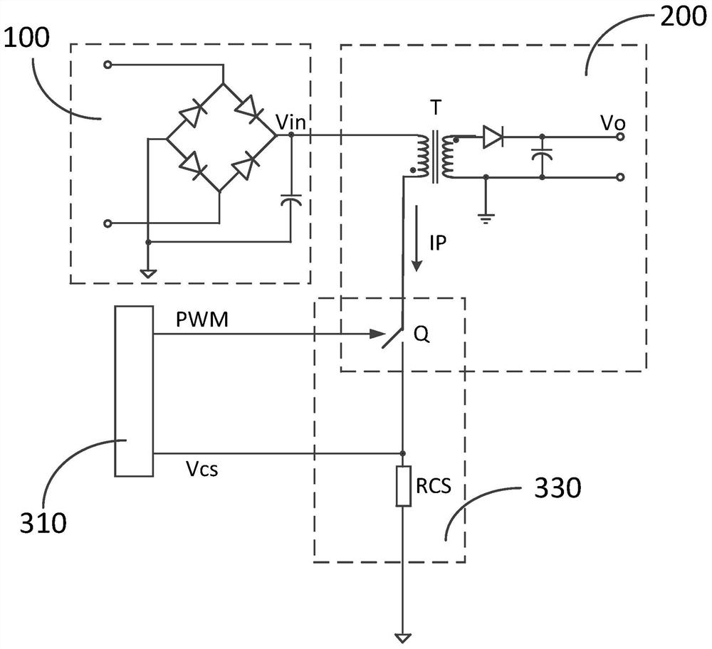
[0037] This embodiment discloses a switch control circuit based on multiplexing of pins, which can simultaneously realize the detection of the detection current IP and the frequency setting of the switch tube Q being turned on and off by using the same group of pins. Wherein, the switch control circuit 310 of this embodiment includes a first pin P1 and a second pin P2. The switch control circuit 310 is coupled to the first circuit 330 . The first pin P1 is used to output the first switch control signal PWM, and the first circuit 330 is controlled by outputting the first switch control signal PWM. The second pin P2 is used to detect and obtain the detection current IP flowing through the first circuit 330 in the first time period, and is used to detect and obtain the element characteristics of the first circuit 330 in the second time period. The switch control circuit 310 controls the first switch control signal PWM according to the detected current IP and device characteristi...
Embodiment 2
[0054] This embodiment discloses a frequency control method based on pin multiplexing, which is applied to the switch control circuit based on pin multiplexing in Embodiment 1, including the following steps:
[0055] The switch control circuit 310 outputs a first switch control signal PWM to control the first circuit 330 . When the first circuit 330 operates in the first time period, the first circuit 330 flows a current, and the current flowing through the first circuit 330 is detected through the first pin P1; when the first circuit 330 operates in the second time period, The characteristics of the components in the first circuit 330 are detected through the first pin P1.
[0056] Changing the frequency of the first circuit 330 between the first time period and the second time period is achieved by changing the characteristics of the components in the first circuit 330 .
[0057] It should be understood that the change of the characteristics of individual components in the ...
Embodiment 3
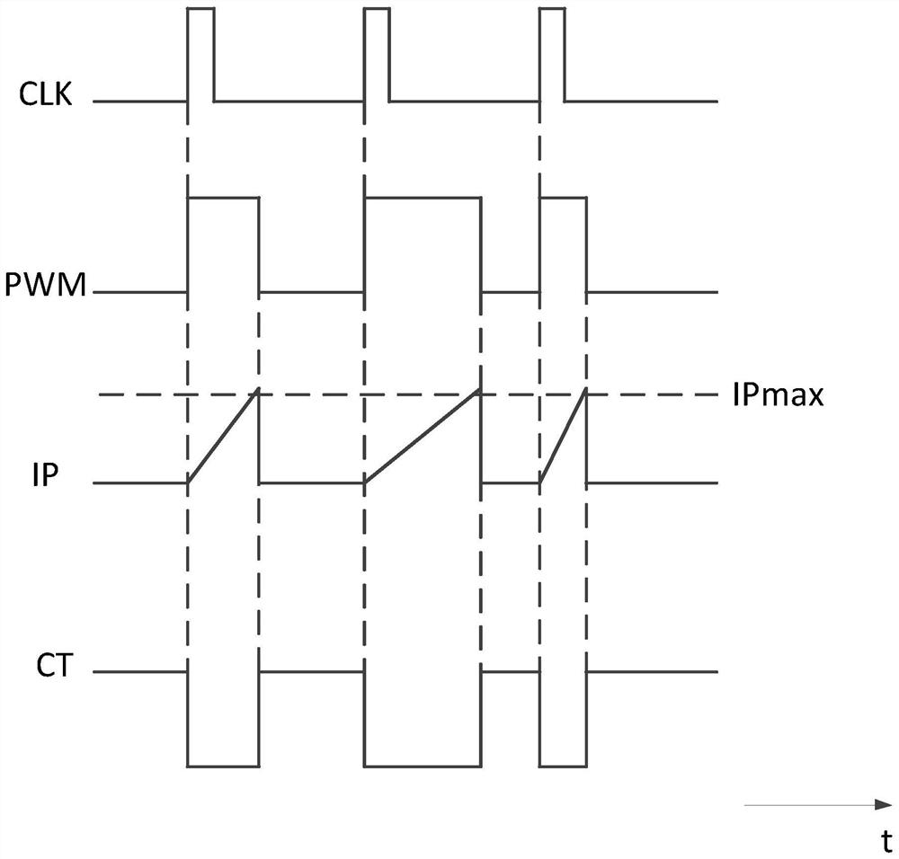
[0060] This embodiment discloses a frequency control method based on pin multiplexing, which is applied to the switch control circuit based on pin multiplexing in Embodiment 1. It is one of the more specific embodiments of Embodiment 2. Refer to the working circuit diagram attached figure 1 , the output of each signal in the working state refers to the attached figure 2 Waveform diagram in . Wherein, the first time stage is the on state of the switch tube Q, and the second time stage is the off state of the switch tube Q, further comprising the following steps:
[0061] Step 1: In the first time period, the switch control circuit 310 outputs a first switch control signal PWM to control the conduction of the switch tube Q at the rising edge of the system clock signal. The frequency of the system clock signal depends on the selection of the resistance value of the detection resistor RCS.
[0062] Step 2: The turned-on switch tube Q makes the detection current IP flow through...
PUM
 Abstract
Description
Claims
Application Information
 - R&D
- Intellectual Property
- Life Sciences
- Materials
- Tech Scout
- Unparalleled Data Quality
- Higher Quality Content
- 60% Fewer Hallucinations
Browse by: Latest US Patents, China's latest patents, Technical Efficacy Thesaurus, Application Domain, Technology Topic, Popular Technical Reports.
© 2025 PatSnap. All rights reserved.Legal|Privacy policy|Modern Slavery Act Transparency Statement|Sitemap|About US| Contact US: help@patsnap.com