Powder spreading device for 3D printer

A 3D printer and powder spreading device technology, applied in the field of 3D printing, can solve the problems of not reducing the workload of cleaning powder, reducing the speed of product development iteration, and reducing the speed of product iteration, so as to reduce repeated work, reduce recycling workload, The effect of reducing workload

Active Publication Date: 2021-07-16
ZHONGBEI UNIV
View PDF15 Cites 2 Cited by
  • Summary
  • Abstract
  • Description
  • Claims
  • Application Information

AI Technical Summary

Problems solved by technology

When these institutions develop products, they usually encounter the situation that the parts are too small and the number is small compared with the substrate, and they will accumulate enough samples before they can start processing, which greatly reduces the speed of product iteration and reduces the production cost. Product R&D Efficiency
[0004] In the existing technical scheme, the authorized announcement number is CN 208357732 U, which is applied to the laying device of 3D printers. Two gear shafts meshing with each other are arranged in the chamber of the blanking bin, and the two gear shafts are arranged on the blanking chamber. On both sides of the discharge port of the bin, the two gear shafts are meshed with each other through the driving mechanism, so that the auxiliary sand in the blanking bin slowly falls, and the meshing distance between the two gear shafts is adjusted through the wheelbase adjustment part, so as to realize the control of the blanking bin. Feeding amount, but this solution cannot determine the feeding amount according to the size of the part. For small batches or slender parts, it cannot reduce the workload of cleaning powder after forming such parts, thereby reducing the iterative speed of product development
[0005] The authorized announcement number is CN 104308148 B, a small metal powder 3D printer powder spreading device, which uses a powder spreading funnel to slide on the forming chamber and sprinkles metal powder in the forming chamber for sintering. The powder is recycled, so that the powder can be recycled, but this solution still cannot solve the problem of a large amount of powder cleaning after the parts are formed, especially for small batches or slender parts, the amount of each forming is too small, and it is impossible to Reasonable powder delivery according to part size

Method used


Image

  • Powder spreading device for 3D printer
  • Powder spreading device for 3D printer
  • Powder spreading device for 3D printer

Examples


Embodiment Construction

[0046] In order to make the technical problems, technical solutions and beneficial effects to be solved by the present invention clearer, the present invention will be further described in detail below in conjunction with the accompanying drawings and embodiments. It should be understood that the specific embodiments described here are only used to explain the present invention, not to limit the present invention.

[0047] It should be noted that when an element is referred to as being “fixed” or “disposed on” another element, it may be directly on the other element or be indirectly on the other element. When an element is referred to as being "connected to" another element, it can be directly connected to the other element or indirectly connected to the other element.

[0048] It is to be understood that the terms "length", "width", "top", "bottom", "front", "rear", "left", "right", "vertical", "horizontal", "top", The orientation or positional relationship indicated by "bot...


PUM


Abstract

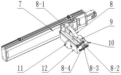
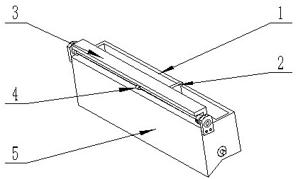
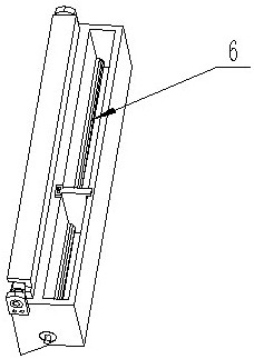
The invention discloses a powder spreading device for a 3D printer. The method comprises the steps that a powder falling module is mounted on one side of a linear motion module and comprises a powder spreading bin, a powder spreading roller, a switch control panel, a cam control shaft and an isolation baffle; a vertical plate is arranged in the powder spreading bin, and the lower end of the vertical plate is separated from a bottom plate of the powder spreading bin; the powder spreading roller is arranged between the lower end of the vertical plate and the bottom plate of the powder spreading bin and divides the powder spreading bin into a powder storage bin and a powder falling bin together with the vertical plate, the two ends of the powder spreading roller are movably mounted in the powder spreading bin, and powder can be conveyed from the powder storage bin to the powder falling bin through rotation of the powder spreading roller; the switch control panel is movably mounted in the powder falling bin and is provided with a boss; a cam is arranged on the cam control shaft and is tangent to the boss, and the two ends of the cam control shaft are movably mounted in the powder falling bin; the isolation baffle is arranged in the powder storage bin and divides the powder storage bin into an empty bin and a powder adding bin. Reasonable powder feeding can be carried out according to the number of parts, the powder cleaning workload is reduced, the iteration speed of product research and development is increased, and the research and development efficiency is improved.

Description

technical field [0001] The invention belongs to the technical field of 3D printing, and in particular relates to a powder spreading device for a 3D printer. Background technique [0002] Laser melting technology, also known as 3D printing technology, or SLM for short, is the most widely used additive manufacturing technology. SLM technology is a technology that uses high-energy laser beams to melt micron-sized metal powders at high speed and solidify them at high speed. The parts formed by SLM technology generally do not require subsequent processing or only simple surface processing, and the mechanical properties of the parts are high, and the density is close to 100%. [0003] The development time of selective laser melting technology is relatively short, and there are fewer companies worldwide that develop this technology and manufacture equipment for it, and there are fewer companies that develop its raw materials (micron-sized metal powder), resulting in the applicatio...

Claims


Application Information

Patent Timeline
Patent Type & Authority Applications(China)
IPC IPC(8): B22F12/60B22F10/31B22F10/73B22F10/28B22F12/67B33Y30/00B33Y40/00
CPCB22F3/003B33Y30/00B33Y40/00
Inventor 白培康李嘉新李忠华杨志成刘斌蒯泽宙路声雨刘立鑫
Owner ZHONGBEI UNIV
Why Eureka
Try Eureka