Fuel cell stack performance recovery method and system

A fuel cell stack and recovery method technology, which is applied in the field of fuel cell stack performance recovery methods and systems, can solve the problems of proton membrane hydrogen gas permeability difference, time difference, irreversible attenuation of electrode catalyst carrier, etc., so as to improve the consistency of reaction activity and safety Efficient performance conditions, the effect of fast and efficient recovery of performance

Pending Publication Date: 2021-07-16
KUSN FUERSAI ENERGY
View PDF0 Cites 1 Cited by
  • Summary
  • Abstract
  • Description
  • Claims
  • Application Information

AI Technical Summary

Problems solved by technology

[0003] However, due to the performance differences of single cells in the fuel cell stack, including the difference in the hydrogen gas permeability of the proton membrane of the single cell, the difference in the catalytic activity of the membrane electrode, the difference in the air atmosphere environment between the middle position and the two sides of the single cell cell, and the difference of the single cell The internal liquid water content is different. Therefore, when the oxidant supply is reduced or stopped when the fuel cell is running, the output voltage of one or more nodes will drop rapidly, the difference in oxygen deficiency in different reaction areas of a single cell will cause unbalanced reactions, or a single cell will appear. Partial water blockage of the membrane electrode, etc., may cause reverse polarity in a single battery or in a local location
At the same time, when the fuel cell stack restores the supply of oxidant, there is still a certain time difference from the supply of oxidant to the filling of the entire cathode cavity of the fuel cell stack. Polarity reversed in battery or local location
The reverse polarity of a fuel cell single cell will cause irreversible decay of the electrode catalyst carrier

Method used


Image

  • Fuel cell stack performance recovery method and system
  • Fuel cell stack performance recovery method and system
  • Fuel cell stack performance recovery method and system

Examples


Embodiment 1

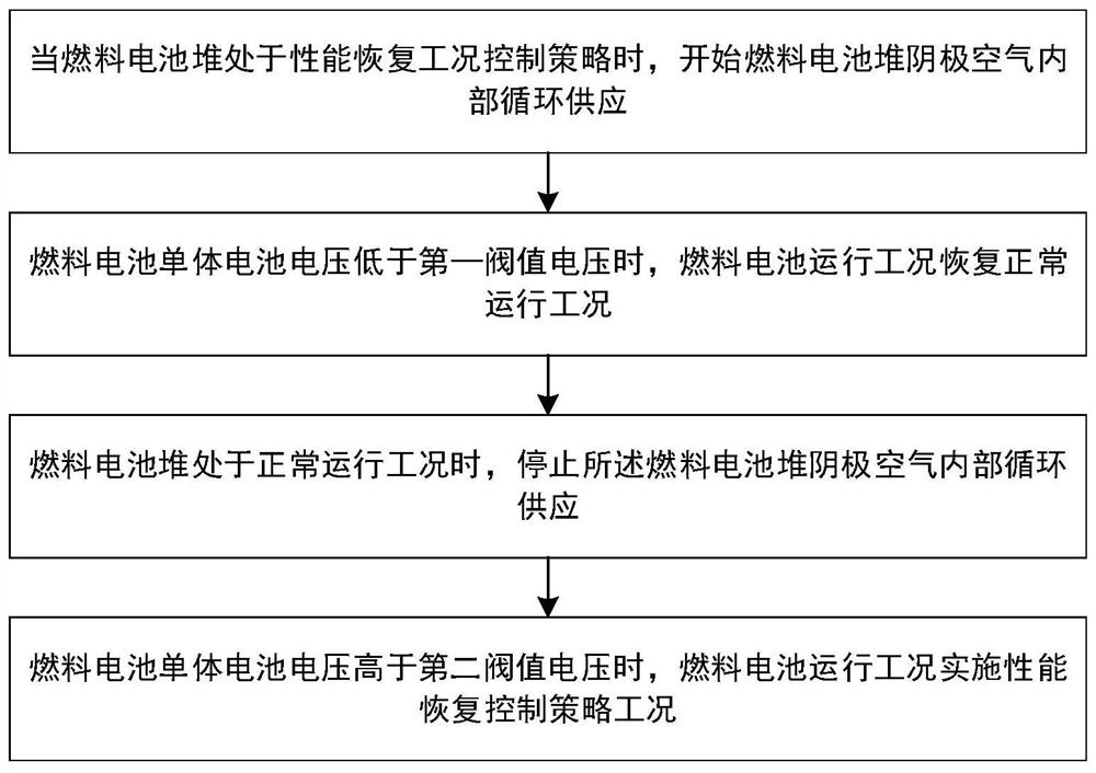
[0031] Embodiment 1 of the present invention provides a fuel cell stack performance recovery method, including the following steps:

[0032] Set up the fuel cell stack cathode air internal circulation supply, and detect the output single cell voltage of the fuel cell stack;

[0033] The fuel cell stack is in the performance recovery condition, and the internal circulation supply of the cathode air of the fuel cell stack is turned on. When it is detected that the voltage of the single cell is lower than the first threshold voltage, the fuel cell stack is switched to the normal operating condition;

[0034] The fuel cell stack is in a normal operating condition, the internal circulation supply of the fuel cell stack cathode air is stopped, and when the voltage of the single cell is detected to be higher than the second threshold voltage, the fuel cell stack is switched to the performance recovery working condition.

[0035] Specifically, when the fuel cell stack is in the perfor...

Embodiment 2

[0039] Embodiment 2 of the present invention provides a fuel cell stack performance recovery system, including a fuel cell stack, a gas supply pipeline, a voltage detection module, and a controller; wherein:

[0040]The air supply pipeline is connected to the cathode of the fuel cell stack and the controller, and is used for supplying air to the cathode of the fuel cell stack and supplying internal circulation of cathode air;

[0041] The voltage detection module is connected to the fuel cell stack and the controller, and is used to detect the output cell voltage of the fuel cell stack and feed back the voltage value to the controller;

[0042] The controller is used to determine whether the output condition of the fuel cell stack is to open the gas supply pipeline to supply the internal circulation of cathode air to switch the operating condition:

[0043] Determine that the fuel cell stack is in the performance recovery condition, control the gas supply line to open the inte...

Embodiment 3

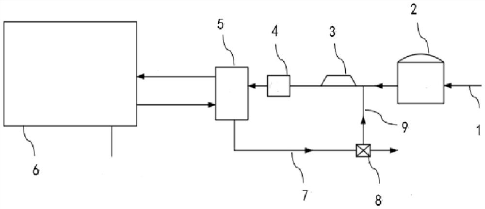
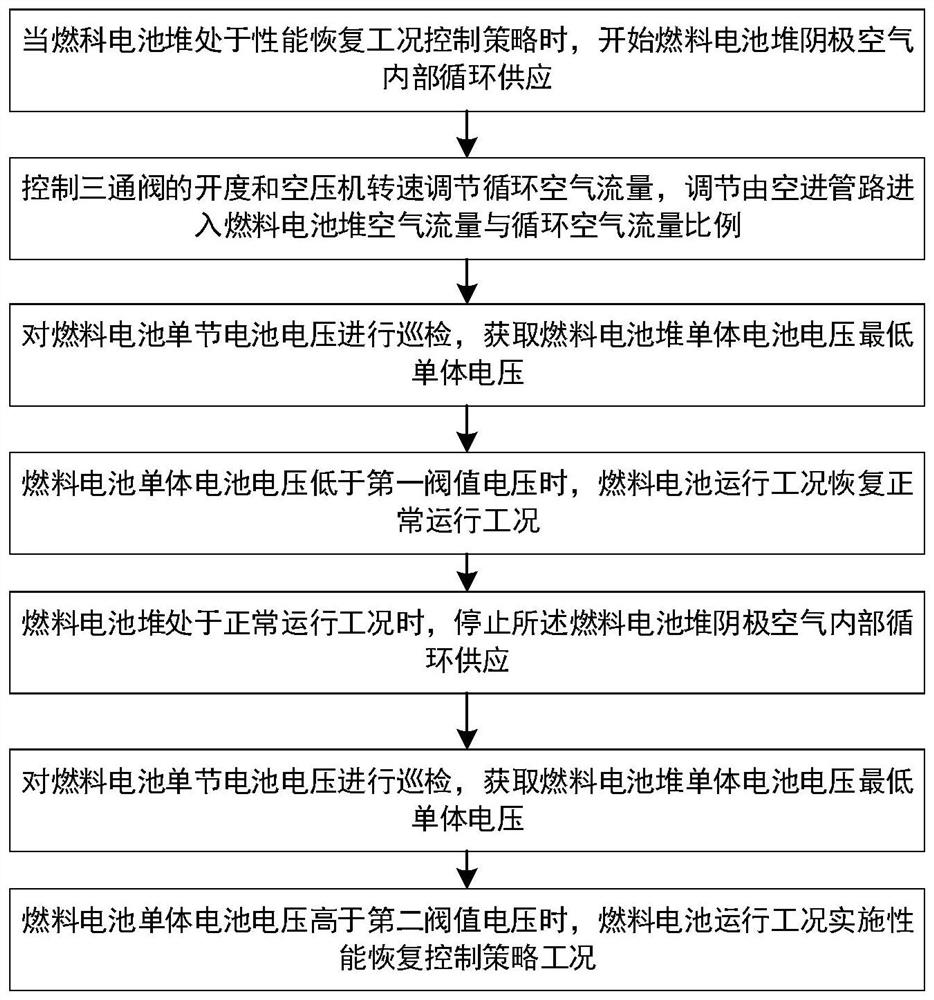
[0050] refer to figure 2 and image 3 , when the fuel cell system executes the performance recovery strategy, the air supply system opens the air tail exhaust circulation valve. Here, the three-way valve 8 is selected to make the tail exhaust air re-enter the stack from the air compressor 3, reducing the oxygen content of the air inside the stack. The self-inspection unit of the system detects the output voltage of the stack. As the reaction continues, the oxygen content of the cathode air of the fuel cell stack 6 further decreases, forming oxygen starvation. The anode hydrogen is "pumped" into the cathode by the hydrogen pump to The oxide film formed on the surface of the cathode catalytic platinum is removed, and the performance of the fuel cell stack 6 is restored according to the removal of the oxide film. By detecting the output cell voltage value of the stack, the control system generates the reaction time of the hydrogen pump. When it is detected that the fuel cell st...


PUM


Abstract

The invention discloses a fuel cell stack performance recovery method and system. The method comprises the following steps: setting fuel cell stack cathode air internal circulation supply, and detecting the voltage of a single cell output by a fuel cell stack; when the fuel cell stack is in a performance recovery working condition, starting internal circulation supply of cathode air of the fuel cell stack, and when it is detected that the voltage of a single cell is lower than a first threshold voltage, switching the fuel cell stack to a normal operation working condition; and when the fuel cell stack is in a normal operation condition, stopping internal circulation supply of cathode air of the fuel cell stack, and when it is detected that the voltage of the single cell is higher than a second threshold voltage, switching the fuel cell stack to a performance recovery condition. According to the invention, the performance of the fuel cell stack is rapidly and efficiently recovered, and the problems of reverse pole and irreversible attenuation of a single fuel cell or a local area are avoided.

Description

technical field [0001] The invention relates to the field of fuel cells, in particular to a fuel cell stack performance recovery method and system. Background technique [0002] At present, the commercial Pt / C catalyst is the main membrane electrode catalyst for proton exchange membrane fuel cells. When the fuel cell is parked for a long time or operated at low power, the surface of the catalyst is easy to form an oxide film on the surface of the metal Pt, resulting in a decrease in the catalytic activity of the catalyst. , resulting in attenuation of the output performance of the fuel cell stack. The existing fuel cell operation control strategy adopts the method of reducing or stopping the oxidant supply of the fuel cell during the operation of the current cell stack, increasing the overpotential of the negative electrode of the cathode, and reducing the output voltage of the fuel cell, which can reduce the oxide coating layer on the surface of the catalyst and achieve the...

Claims


Application Information

Patent Timeline
IPC IPC(8): H01M8/04223H01M8/04537H01M8/04746
CPCH01M8/04238H01M8/04552H01M8/04753Y02E60/50
Inventor 王文智张超管俊生夏冬冬陶安文戴俊
Owner KUSN FUERSAI ENERGY
Why Eureka
Try Eureka