Unmanned aerial vehicle battery suitable for automatically replacing platform

An automatic battery replacement technology, applied in the field of drones, can solve the problems of inconvenient disassembly and assembly of drone batteries, and achieve the effect of accurate battery replacement process and saving manpower and material resources.

Inactive Publication Date: 2021-07-16
TIANJIN UNIV
View PDF5 Cites 1 Cited by
  • Summary
  • Abstract
  • Description
  • Claims
  • Application Information

AI Technical Summary

Problems solved by technology

[0003] The purpose of the present invention is to solve the problem of inconvenient disassembly and assembly of drone batteries existing in the prior art, and to provide a drone battery suitable for automatic replacement platforms

Method used


Image

  • Unmanned aerial vehicle battery suitable for automatically replacing platform
  • Unmanned aerial vehicle battery suitable for automatically replacing platform
  • Unmanned aerial vehicle battery suitable for automatically replacing platform

Examples


Embodiment 1

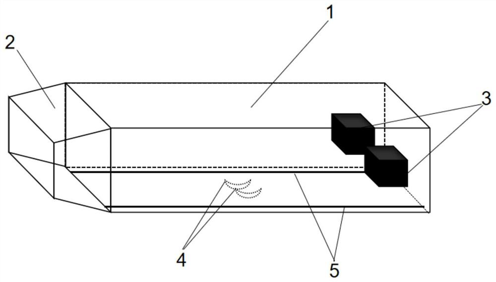
[0027] An unmanned aerial vehicle battery suitable for automatic replacement platforms, including a battery inner compartment 6 fixed on the unmanned aerial vehicle and a battery body 1 that can be matched and inserted into the battery inner compartment 6, wherein:

[0028] The side of the battery inner compartment 6 is formed with an opening 9 for the battery body 1 to enter and exit, and the bottom surface of the battery inner compartment 6 is fixed with a contact electrode 7 electrically connected to the drone;

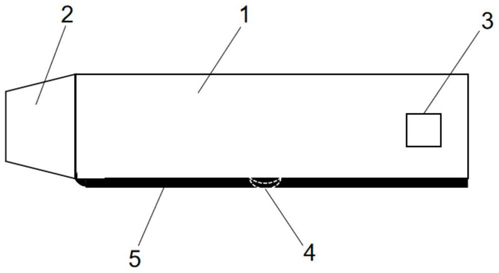
[0029] The head end of the battery body 1 is formed with a self-correcting structure 2, and a paddle-type contact electrode 4 is fixed on the bottom surface of the battery body 1, and the paddle-type contact electrode 4 is in contact with the contact electrode 7 for power supply;

[0030] The corresponding surfaces of the battery inner compartment 6 and the battery body 1 are respectively provided with matching guide grooves 8 and guide bars 5, and the tail end of t...

Embodiment 2

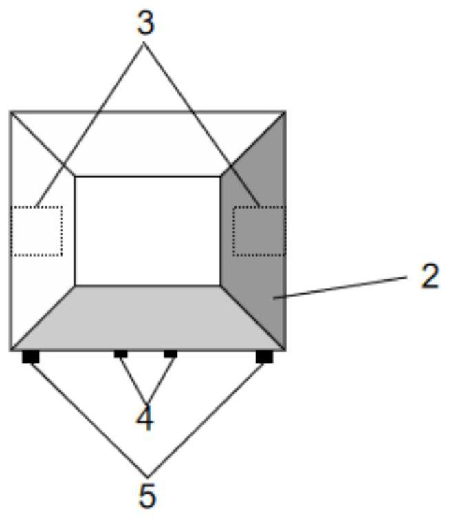
[0033] In order to improve the self-correcting performance of the self-correcting structure 2, the battery inner compartment 6 is a housing with a rectangular parallelepiped structure, and the self-correcting structure 2 is a quadrangular truss structure formed on the battery body 1, and the quadrangular truss structure The four trapezoidal inclined surfaces are all guiding surfaces, and the rear part of the battery body 1 is a cuboid structure.

[0034] Since the automatic correcting structure 2 is a truss structure with trapezoidal slopes on all sides, during the pushing process, the position correction of the battery body 1 is automatically completed due to the thrust and the extrusion force of the slope; the automatic correcting structure is completely inserted into the battery inner compartment 6 Finally, at this time, the cross section of the rectangular parallelepiped battery 1 coincides with the cross section of the inner compartment 6 of the battery.

[0035] After th...

Embodiment 3

[0040] In order to facilitate the clamping of the manipulator, two embedded card slots 3 are provided, and the two embedded card slots 3 are respectively formed on two opposite sides of the tail of the battery body 1 . When the battery body 1 is inserted into the battery inner compartment 6, the embedded card slot 3 is located outside the battery inner compartment 6, which is convenient for the manipulator to grip.

[0041] More preferably, the two embedded card slots 3 are square slots, which cooperate with the square blocks fixed on the two fingers of the manipulator, so as to be convenient for the manipulator to grip. The inside of the finger is equipped with a block with the same inner diameter as the embedded card slot 3. The manipulator opens two fingers and moves to face the embedded groove. After the fingers are closed, the block is slowly inserted into the battery embedded groove 3. Complete the battery clamping, move the position of the manipulator to complete the in...


PUM


Abstract

The invention discloses an unmanned aerial vehicle battery suitable for automatically replacing a platform. The unmanned aerial vehicle battery comprises a battery inner bin fixed on an unmanned aerial vehicle and a battery body which can be inserted into the battery inner bin in a matched manner, wherein an opening through which the battery body enters and exits is formed in the side portion of the battery inner bin, a contact electrode electrically connected with the unmanned aerial vehicle is fixed on the bottom surface of the battery inner bin, a self-correcting structure is formed at the head end of the battery body, a shifting piece type contact electrode is fixed on the bottom surface of the battery body, the shifting piece type contact electrode is in contact with the contact electrode to supply power, the corresponding surfaces of the battery inner bin and the battery body are respectively provided with a guide groove and a guide strip which are matched with each other, and an embedded clamping groove matched with a replacement mechanism is formed in the tail end of the battery body. According to the invention, automatic accurate positioning and rapid charging can be realized.

Description

technical field [0001] The invention relates to the technical field of unmanned aerial vehicles, in particular to an unmanned aerial vehicle battery suitable for automatic platform replacement. Background technique [0002] With the continuous improvement of electronic technology and automatic control technology, unmanned aerial vehicles have developed rapidly in military and civilian fields, especially in agriculture, geological exploration, emergency rescue, frontier defense and other industries. Now drone operation, its battery life can not meet the long-term operation, and the time of wired or wireless charging can not meet the requirements of short-term continuous work, and most of them use manual recycling, and continue to work after replacing the battery. However, the existing drone batteries and battery inner compartments are too complicated to replace the platform, and it is difficult to fix and replace them with a manipulator. Contents of the invention [0003] ...

Claims


Application Information

Patent Timeline
IPC IPC(8): H01M50/244H01M50/298
CPCY02E60/10
Inventor 邹强柳旭
Owner TIANJIN UNIV
Why Eureka
Try Eureka