Sliding block structure and forming die of haircut knife blade
A technology for molding molds and barbers, which is applied to casting molding equipment, molds, cores, etc., can solve problems such as cloaks and parting lines, and achieve the effects of prolonging service life, reducing maintenance times, and improving work efficiency
- Summary
- Abstract
- Description
- Claims
- Application Information
AI Technical Summary
Problems solved by technology
Method used
Image

Examples
Embodiment 1
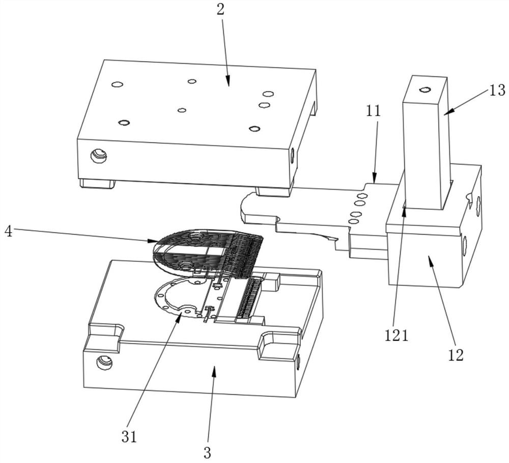
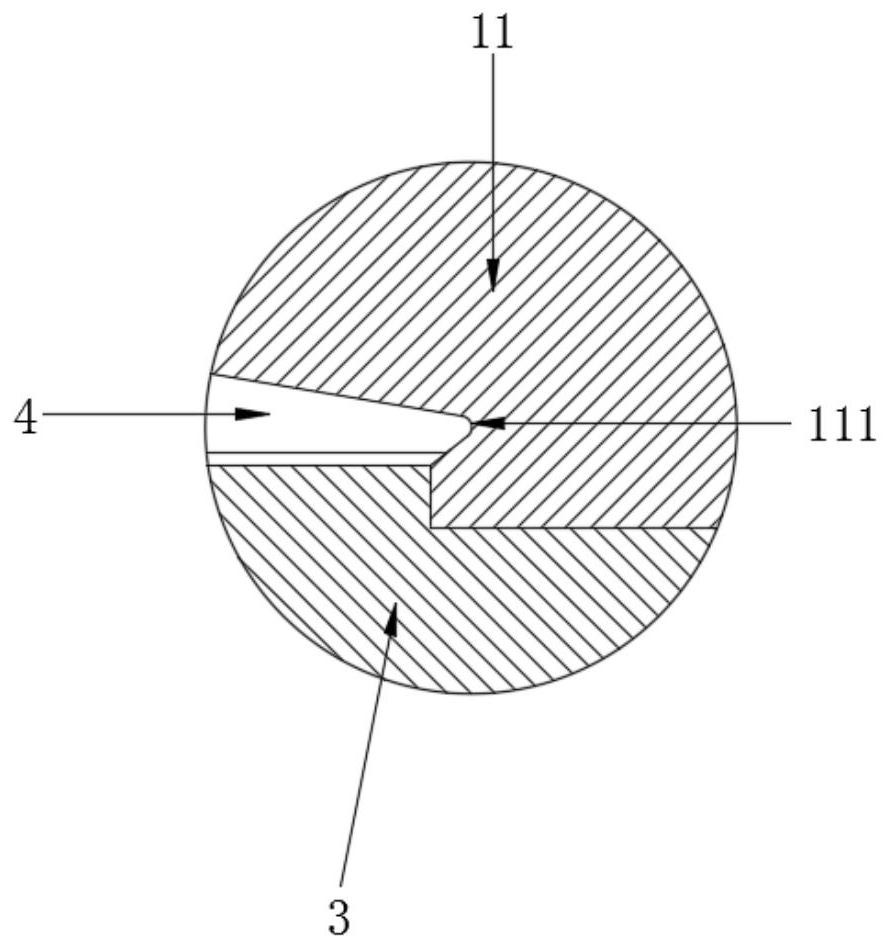
[0036] refer to Figure 1 to Figure 5 , this embodiment mentions a slider structure, including a slider insert 11, the slider insert 11 is located between the upper mold core 2 and the lower mold core 3, the slider insert 11, the upper mold core 2 And the lower mold core 3 can be combined together after closing the mold, jointly enclosing and forming the forming cavity of the barber blade 4, the forming cavity matches the overall shape of the barber blade 4, and the front end of the barber blade 4 is round Arc-shaped, the slider insert 11 is provided with a first forming part 111 matching the shape of the front end of the barber blade 4 at the corresponding position of the front end of the barber blade 4, and the shape of the front end of the barber blade 4 is controlled by the first forming part 111. Forming shape, forming a completely wrapped state, changing the position of the parting line, and moving the parting line down to other parts, so that the product no longer has a...
Embodiment 2
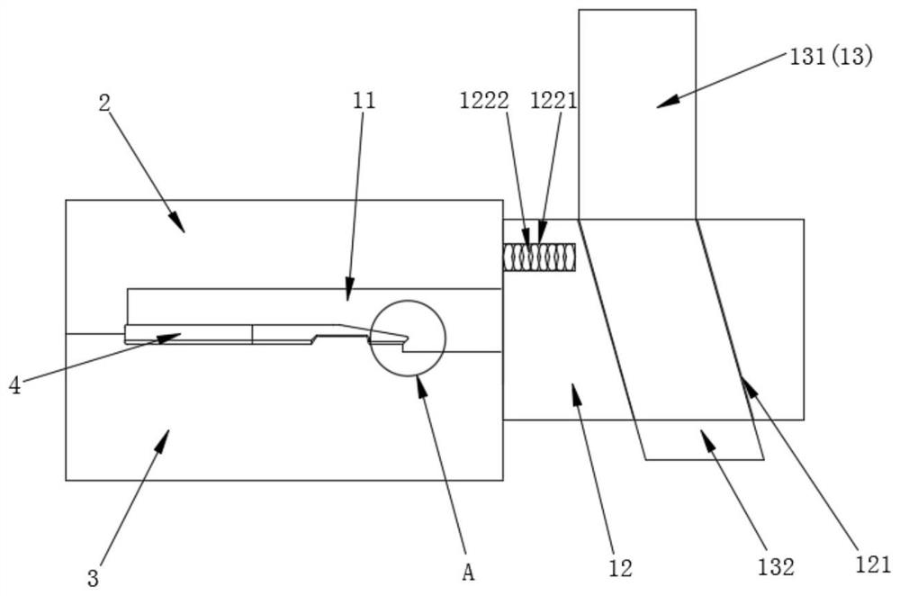
[0038]On the basis of the above embodiments, as an optional implementation, the slider structure further includes a slider body 12 and a slider wedge 13, the slider body 12 is connected to the slider insert 11, and the connection here is preferably a bolt Connection, easy to disassemble, when the slider insert 11 reaches the useful life or its own structure is damaged, it is easier to replace the slider insert 11 alone, saving costs, the slider body 12 is provided with a wedge groove 121, The slider wedge 13 is inserted in the wedge groove 121, and the slider wedge 13 and the wedge groove 121 cooperate with each other through the basic principle of the wedge structure so that when the slider wedge 13 moves relative to the wedge groove 121, the Drive the slider body 12 to move in different directions, and the degree of automation is higher. Specifically, when the slider wedge 13 moves downward after being subjected to external force, it can drive the slider body 12 toward the up...
Embodiment 3
[0040] On the basis of the above-mentioned embodiments, as an optional implementation, the rebound structure 122 includes a movable groove 1221 and a spring 1222, and the slider body 12 is provided with a movable groove 1221, and the number of the movable groove 1221 is at least one, and each movable The grooves 1221 are all connected to one end of a spring 1222. When the mold is closed, the slider body 12 will abut against the upper mold core 2, so the other end of the spring 1222 is positioned outside the movable groove 1221 in a natural state and is in contact with the mold core 2. The upper mold core 2 is in contact with each other. When the mold is closed, the spring 1222 is compressed. When the mold is opened, the spring 1222 resets, driving the slider body 12 to move away from the upper mold core 2 and the lower mold core 3. The spring 1222 has a good The elasticity is beneficial to the rebound of the slider body 12. In this embodiment, the number of movable grooves 1221...
PUM
 Abstract
Description
Claims
Application Information
 - R&D
- Intellectual Property
- Life Sciences
- Materials
- Tech Scout
- Unparalleled Data Quality
- Higher Quality Content
- 60% Fewer Hallucinations
Browse by: Latest US Patents, China's latest patents, Technical Efficacy Thesaurus, Application Domain, Technology Topic, Popular Technical Reports.
© 2025 PatSnap. All rights reserved.Legal|Privacy policy|Modern Slavery Act Transparency Statement|Sitemap|About US| Contact US: help@patsnap.com