
Slip ring U-screw machining tool and using method

A slip ring and screw technology, which is applied in the field of slip ring processing, can solve the problems that the electric slip ring is easy to slide on the motor shaft, the installation stability of the electric slip ring and the motor shaft is not good, and affects the practicality, so as to achieve the stability of fixed installation High, good fixing effect, fast positioning efficiency

Pending Publication Date: 2021-07-23
上海昂电电机有限公司
View PDF0 Cites 0 Cited by
  • Summary
  • Abstract
  • Description
  • Claims
  • Application Information

AI Technical Summary

Problems solved by technology

[0004] The purpose of the present invention is to solve the problem that when the electric slip ring is installed on the motor shaft, the installation stability of the electric slip ring and the motor shaft is not good, and the electric slip ring is easy to slide on the motor shaft during use. Affect the subsequent practical problems, and the proposed slip ring riding screw processing tooling

Method used


Image

  • Slip ring U-screw machining tool and using method
  • Slip ring U-screw machining tool and using method
  • Slip ring U-screw machining tool and using method

Examples


Embodiment

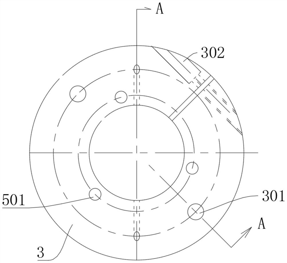
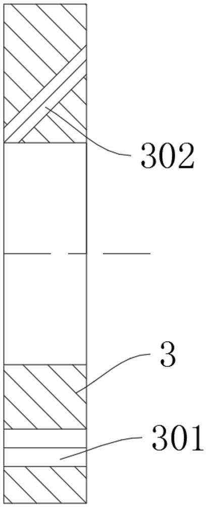
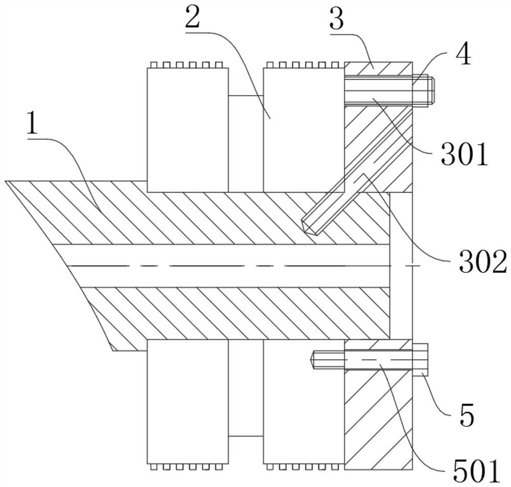
[0025] Refer Figure 1-3 Slip ring riding screw machining tooling, comprising: a motor shaft, the center of the slip ring shaft 2, the socket member; sheathing slip ring member on the motor shaft 2; slip-ring sleeved on the motor shaft 1 is fixed spiro hole positioning plate 3, the slip ring for clamping the fixing member 2; wherein the slip ring element is provided between the positioning member 32 and the sliding ring retainer screw positioning plate processing, is to be understood that the positioning member comprising: a positioning plate die hole 301 provided on the sliding ring fixing screw machining positioning plate 3; slip ring bolt connection 4, is fixedly connected to the slip ring element 2, inserted in the die plate locating holes 301, the positioning member is provided with two sets of symmetrical, in the slip ring 3 fixed to the socket screw holes when the plate is positioned on the working axis motor 1, the slide ring is fixed screw machining positioning plate 3 and...


PUM


Abstract

The invention discloses a slip ring U-screw machining tool, and belongs to the field of slip ring machining. The slip ring U-screw machining tool comprises a motor shaft, a slip ring piece sleeving the motor shaft, a slip ring fixing screw hole processing positioning plate sleeving the motor shaft and used for clamping and fixing the slip ring piece, and a fixing screw hole groove, a positioning component is arranged between the slip ring piece and the slip ring fixing screw hole machining positioning plate; the fixing screw hole groove sequentially penetrates through the slip ring fixing screw hole machining positioning plate, the slip ring piece and the motor shaft; and fixing bolts used for fixing the motor shaft, the slip ring piece and the slip ring fixing screw hole machining positioning plate are connected into the fixing screw hole groove. Through arrangement of the slip ring fixing screw hole machining positioning plate, the slip ring piece positioning efficiency is high, the mounting efficiency is high, and the fixing effect is better.

Description

Technical field [0001] The present invention relates to a slip ring processing technology, and more particularly relates to a slip ring saddle screw machining tooling and methods of use. Background technique [0002] Slip ring is used to electrically conductive slip ring used in all series, the most widely slip ring, also known as a brush, brush, slip ring, the slip ring, the ring bus, through the rotation, the rotating electrical joint, in the absence of dedicated when the continuous rotation limit, the transmission power of the power supply signal. [0003] When the conventional slip ring mounted on the motor shaft, mounted easily lead to poor stability of the motor shaft and the slip ring, the slip ring leads slippery in use in the motor shaft, affect the subsequent practical. Inventive content [0004] Object of the present invention is to solve the conventional electrical slip ring mounted on the motor shaft, mounted easily lead to poor stability of the motor shaft and the ...

Claims


Application Information

Patent Timeline
Patent Type & Authority Applications(China)
IPC IPC(8): B25B11/00
CPCB25B11/00
Inventor 蒋新根陆文龙雷万官何杰韩劲松陶钧
Owner 上海昂电电机有限公司
Learn More