Winding device for engineering machinery

A hoisting device and construction machinery technology, which is applied in the direction of hoisting device, clockwork mechanism, cleaning method and utensils, etc., can solve the problems of inability to change the winding speed, lack of steel wire rope rust cleaning, poor winding efficiency, etc.

Active Publication Date: 2021-07-23
湖北恒子工程技术有限公司
View PDF4 Cites 0 Cited by
  • Summary
  • Abstract
  • Description
  • Claims
  • Application Information

AI Technical Summary

Problems solved by technology

[0005] The purpose of the present invention is to solve the problem that the winding mechanism on the existing hoisting device exists in the prior art when winding the steel wire rope. The efficiency is poor, and the speed of winding cannot be changed, which has certain limitations; and the steel wire rope will be stained with rust due to long-term use, and lacks the shortcomings of cleaning the rust of the steel wire rope, so a hoisting device for construction machinery is proposed

Method used


Image

  • Winding device for engineering machinery
  • Winding device for engineering machinery
  • Winding device for engineering machinery

Examples


Embodiment Construction

[0024] The following will clearly and completely describe the technical solutions in the embodiments of the present invention with reference to the accompanying drawings in the embodiments of the present invention. Obviously, the described embodiments are only some, not all, embodiments of the present invention.

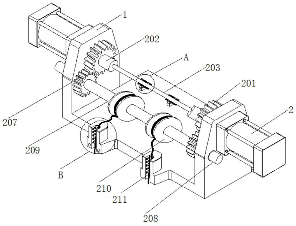
[0025] refer to Figure 1-5 , a hoisting device for construction machinery, comprising a winding frame 1, the top of the winding frame 1 is provided with a winding mechanism, and one side of the winding frame 1 is provided with a derusting mechanism;

[0026] The rewinding frame 1 provided facilitates the formation of the main body of the rewinding mechanism, the provided rewinding mechanism facilitates rewinding the steel wire rope 211, and the provided derusting mechanism facilitates removal of rust on the surface of the steel wire rope 211.

[0027] Preferably, the winding mechanism includes a rotating motor 2 located on the outer wall of the winding frame 1, the ...


PUM


Abstract

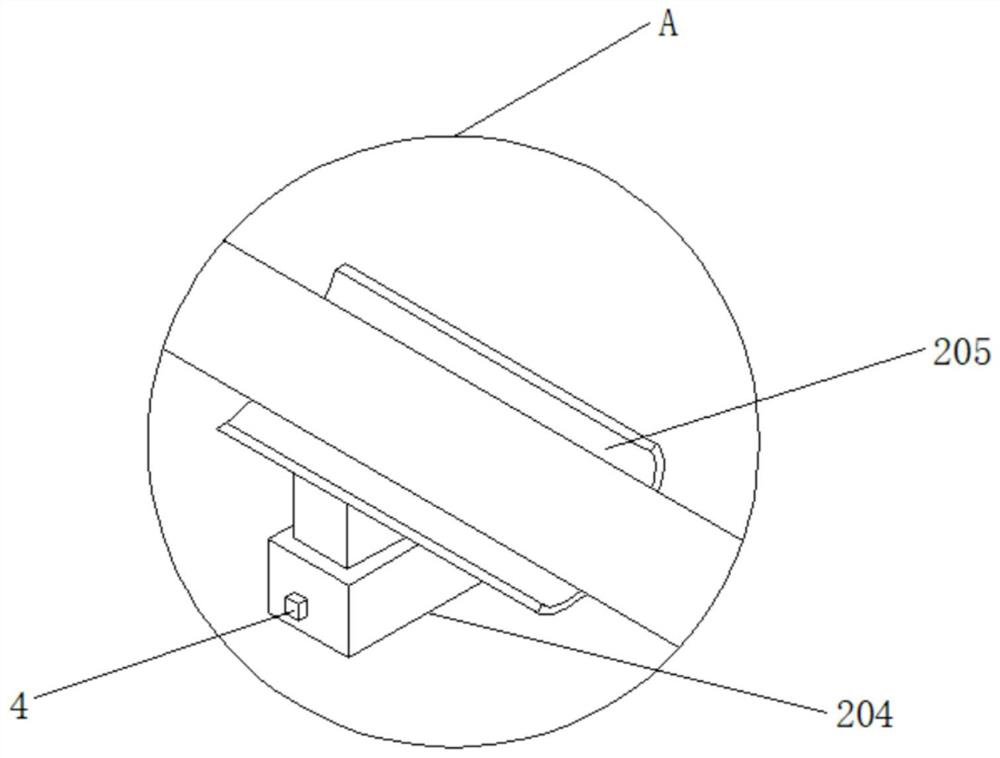
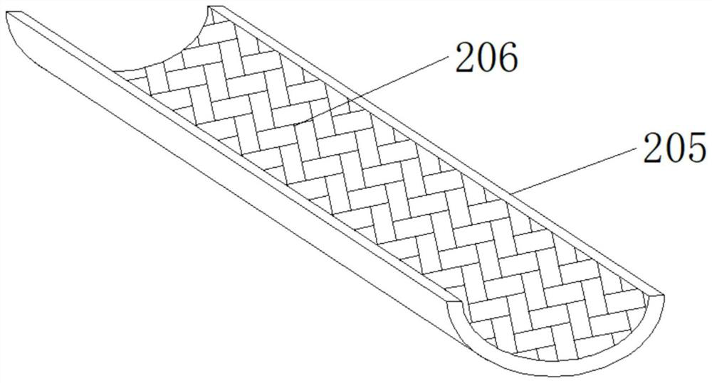
The invention relates to the technical field of mechanical engineering, in particular to a winding device for engineering machinery. The device comprises a winding frame, a winding mechanism is arranged at the top of the winding frame, a rust removal mechanism is arranged at one side of the winding frame, and the winding mechanism comprises a rotating motor located on the outer wall of the winding frame. The output end of the rotating motor penetrates through the winding frame and extends to the inner side of the winding frame, the output end of the rotating motor is connected with a driving gear, and one side of the driving gear is fixedly connected with a rotating cylinder. The winding device has the beneficial effects that the driving gear drives a driven gear to rotate, a rotating shaft is beneficial to providing of supporting force for the driven gear during rotation, the driven gear can drive a connecting column and a winding cylinder to rotate, the winding cylinder drives a steel wire rope to wind, when the winding speed needs to be changed, a starting switch is turned on, a lifting column drives an arc-shaped plate to ascend, a friction layer in the arc-shaped plate makes contact with a speed reduction rod, and the rotating speed of the speed reduction rod is reduced under the friction effect.

Description

technical field [0001] The invention relates to the technical field of mechanical engineering, in particular to a winch device for engineering machinery. Background technique [0002] The hoisting device is a light and small lifting device that uses a reel to wind a wire rope or chain to lift or pull heavy objects, also known as a winch. The hoisting device can lift heavy objects vertically, horizontally or obliquely. The hoisting device is divided into manual hoisting , electric hoist and hydraulic hoist, mainly electric hoist, which can be used alone or as a component of machinery such as lifting, road construction and mine hoisting. Easy to install and widely used, it is mainly used for material lifting or flat dragging in construction, water conservancy projects, forestry, mines, docks, etc. [0003] The hoisting device converts electric energy into mechanical energy through the motor, that is, the rotor of the motor rotates and outputs, and then the reel rotates to dri...

Claims


Application Information

Patent Timeline
Patent Type & Authority Applications(China)
IPC IPC(8): B66D1/12B66D1/30B66D1/40B08B3/08
CPCB66D1/12B66D1/30B66D1/40B08B3/08B08B3/041
Inventor 冉光超
Owner 湖北恒子工程技术有限公司
Why Eureka
Try Eureka