Multi-tube pulse knocking engine with stable exhaust device

A pulse detonation and engine technology, which is applied to machines/engines, gas turbine devices, mechanical equipment, etc., can solve the problems of weakening gas pulsation characteristics and low nozzle efficiency, and achieves weakening pulsation characteristics, improving work efficiency and reducing thrust loss. Effect

Active Publication Date: 2021-07-23
NORTHWESTERN POLYTECHNICAL UNIV
View PDF9 Cites 1 Cited by
  • Summary
  • Abstract
  • Description
  • Claims
  • Application Information

AI Technical Summary

Problems solved by technology

[0006] Aiming at the low efficiency of conventional nozzles caused by gas pulsation at the outlet of the combustion chamber in current pulse detonation engines, the present invention proposes a multi-tube pulse detonation engine with smooth exhaust. Entering the nozzle, the pulsation characteristics of the gas are weakened by the buffering effect of the plenum chamber, and the thrust loss caused by the over-expansion or under-expansion of the exhaust gas is reduced when the fixed-geometry nozzle is used

Method used


Image

  • Multi-tube pulse knocking engine with stable exhaust device
  • Multi-tube pulse knocking engine with stable exhaust device
  • Multi-tube pulse knocking engine with stable exhaust device

Examples


Embodiment 1

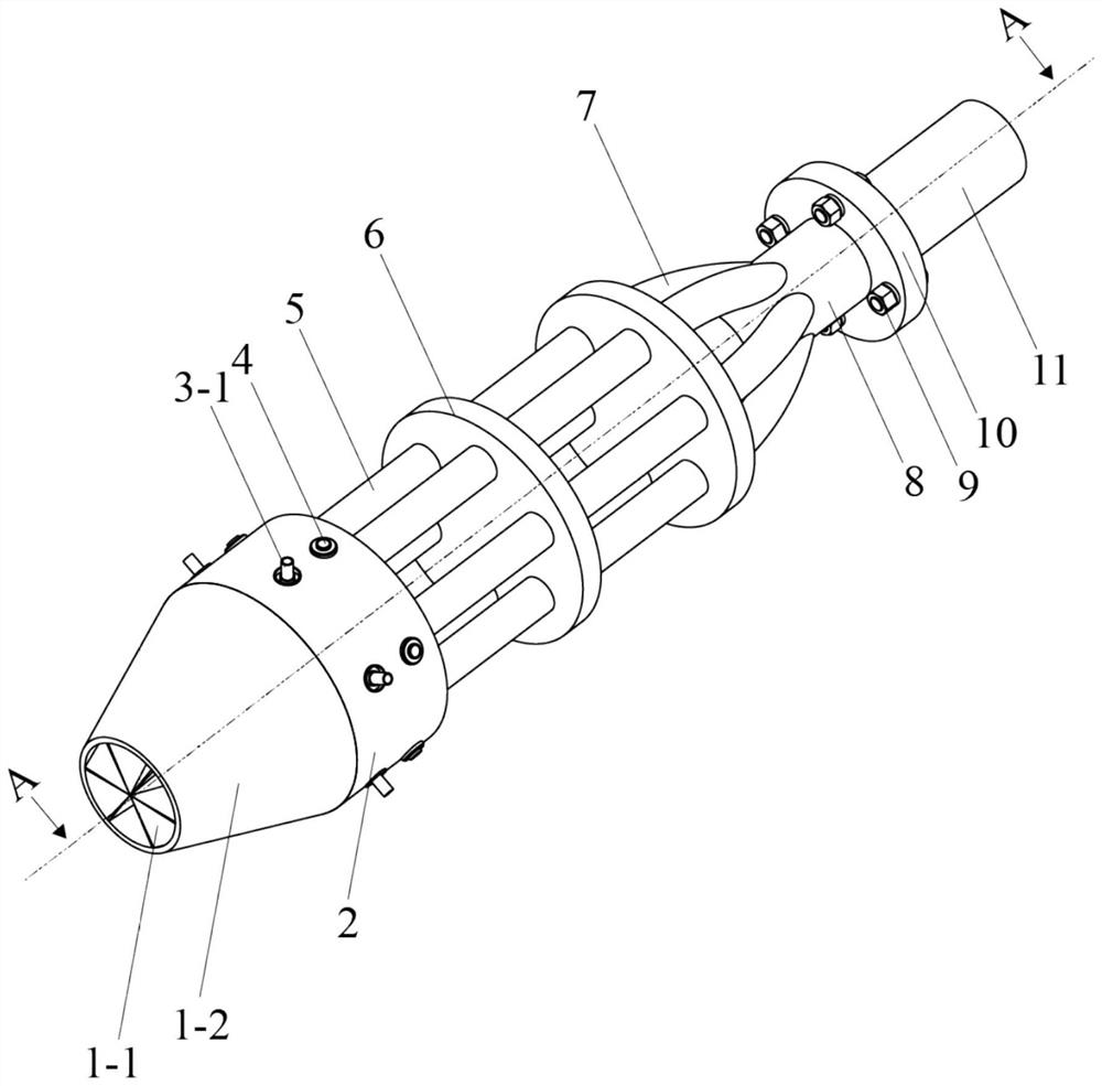
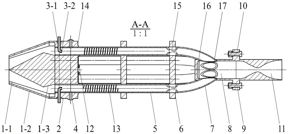
[0030] see figure 1 and figure 2 , this example works with suction, the outer bottom surface of the combustion chamber head 2 is equipped with an intake partition 1-1, an intake cover 1-2 and an intake cone 1-3, which jointly form an air intake passage, and the fuel flows from The fuel supply channel 3-1 feeds and injects into the detonation tube 5 through the nozzle 3-2. The number of detonation tubes 5 in the detonation combustion chamber is 6, and the number of support frame main bodies 6 is 2.

Embodiment 2

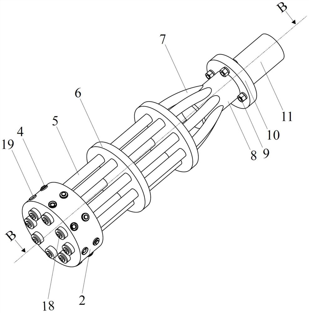
[0032] see image 3 and Figure 4 , the present example works in a rocket manner, the head of each detonation tube 5 is equipped with a fuel injection port 18, and the fuel is injected into the detonation tube 5 along the axial direction, and the oxidant is supplied from the oxidant supply channel 19 of the side wall of the tube along the direction perpendicular to the detonation tube. The direction of the tube 5 axis is injected into the detonation tube 5 . The number of detonation tubes 5 in the detonation combustion chamber is 8, and the number of support frame main bodies 6 is 2.


PUM


Abstract

The invention provides a multi-tube pulse knocking engine with a stable exhaust device. The engine comprises a knocking combustion chamber, a pressure stabilizing section and an exhaust nozzle. According to the engine, fuel gas is exhausted from knocking pipes and then enters the exhaust nozzle through the pressure stabilizing section, the pulsation characteristic of the fuel gas is weakened by the buffering effect of a pressure stabilizing cavity in the pressure stabilizing section, and thrust loss caused by exhaust over-expansion or under-expansion when a fixed geometric nozzle is adopted is reduced. The pressure stabilizing cavity has the specific effects that firstly, the section area of a flow channel of the pressure stabilizing cavity is larger than that of the knocking pipes, the fuel gas expands and decelerates after entering the pressure stabilizing cavity, then the pressure gradient in the fuel gas is reduced, in addition, when a shock wave structure generated by knocking combustion enters the pressure stabilizing cavity, diffraction occurs at the sudden expansion position of the section of the flow channel, the strength of shock waves is greatly weakened, and therefore pressure oscillation caused by the shock waves is abated; and secondly, the pressure stabilizing cavity is the confluence of the flow directions of the fuel gas in all the knocking pipes, and under the condition that all the knocking pipes work cooperatively, the pressure in the cavity can be always kept near the peak value. On the basis of the two points, the purposes of stabilizing the incoming flow pressure of the nozzle and improving the working efficiency of the nozzle are achieved. The engine can be applied to the fields of knocking propulsion and the like.

Description

technical field [0001] The invention relates to the fields of detonation propulsion and the like, in particular to a multi-tube pulse detonation engine with smooth exhaust. Background technique [0002] Pulse detonation engine (Pulse Detonation Engine, referred to as PDE) is an engine that uses periodic detonation combustion to generate thrust. Compared with conventional jet engines based on isobaric combustion, PDE has the potential advantage of high thermal cycle efficiency; detonation The combustion process can realize self-supercharging, so the heavy and complicated supercharging parts can be saved, and the structure is simpler. In view of the above advantages, the pulse detonation engine is a new type of power device with application prospects. [0003] The working principle of PDE determines that the gas at the outlet section of the combustion chamber has strong pulsation characteristics. The self-pressurization characteristic of the detonation wave can increase the ...

Claims


Application Information

Patent Timeline
IPC IPC(8): F02K7/075F02C3/14F02C7/264
CPCF02K7/075F02C3/14F02C7/264
Inventor 王可郭俊睿于潇栋夏家兴刘璐璐
Owner NORTHWESTERN POLYTECHNICAL UNIV
Why Eureka
Try Eureka