Automatic control drying equipment for microwave chemical fiber paper tube processing

An automatic control, chemical fiber paper tube technology, applied in lighting and heating equipment, heating to dry solid materials, drying solid materials, etc. The effect of avoiding moth and mildew

Inactive Publication Date: 2021-07-23
李香珍
View PDF3 Cites 2 Cited by
  • Summary
  • Abstract
  • Description
  • Claims
  • Application Information

AI Technical Summary

Problems solved by technology

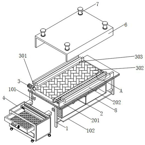
The utility model is equipped with an operation box, a working box, a motor, a first helical gear, a second helical gear, a fixed column, a first disc, a first bearing, a net box, a box door, a second disc, a connecting column and a second The second bearing solves the problem that the existing drying box cannot evenly dry the paper tube, resulting in the paper tube being too dry or wet. The paper tube drying box for paper tube production has the ability to evenly dry the paper tube It improves the practicability of the drying box and is convenient for users to use”, but this device fails to consider the need to detect the humidity of the dried paper tube after drying the paper tube, and the drying effect of the test device is good damaged, and it is impossible to transfer and collect the dried paper tubes of the device, lacking the corresponding transfer collection and detection reminder effect;
[0005] 2. The comparative document CN211763849U discloses a paper tube drying box for paper tube production, "comprising a box body, a hot air blower and a motor, the box body is fixedly installed on the base, and the universal wheels are installed at the bottom of the base, so the The hot air blower has an air inlet end and an air outlet end, and the base is provided with a drying bin, a transmission bin and an equipment bin from top to bottom, the hot air blower and the motor are fixedly installed in the equipment bin, and the drying chamber The top opening of the dry bin is hinged with a top cover, and a number of support shafts are rotatably installed in the drying bin. The outer surface of the support shaft is provided with a tensioning sleeve, and the axes of the several support shafts are located on the same circumferential surface. Above, the support shaft is connected to the motor through a transmission assembly, and an air outlet pipe is fixedly connected to the central position in the drying chamber, and the air outlet pipe is connected to the air outlet end of the hot air blower. There are several vertical ventilation slots on the outer wall of the air outlet pipe, and there are air outlets installed on the drying chamber. However, when the device is drying the paper tubes, it adopts a continuous drying method, which may easily cause the paper tubes to dry out. Excessive, it makes the paper tube brittle, affects the quality of the paper tube, and cannot kill the germs and insect eggs remaining inside the paper tube, which may cause mildew and insect damage to the paper tube in subsequent use;
[0006] 3. The comparative document CN212205474U discloses a paper tube drying box for paper tube production, "comprising a box body, a drive chamber is provided at the bottom of one side wall of the box body, a drive motor is provided in the drive chamber, and the drive motor There is a first transmission shaft on the top, the inner cavity of the box is provided with a support and a second transmission shaft, the bottom of the support is fixedly connected with the bottom of the inner cavity of the box, and the top of the second transmission shaft is provided with a supporting shaft , a paper tube body is provided on the outside of the support shaft body, a support assembly is provided between the support shaft body and the paper tube body, and the support assembly includes an arc-shaped bearing bush, a spring tube and a support column, and the box body Both side walls are provided with a first rotating motor, the first rotating motor is provided with a first rotating shaft, and the output end of the first rotating shaft is provided with fan blades, and the top of the box is provided with a drying box. The top of the drying box is equipped with a second rotating motor. The utility model has a good drying effect, can support the paper tube to prevent deformation, and improves the quality of the paper tube production. The paper tube is then rotated to achieve uniform drying of the paper tube, but manual replacement of the paper tube socket is required, and the drying efficiency is low

Method used


Image

  • Automatic control drying equipment for microwave chemical fiber paper tube processing
  • Automatic control drying equipment for microwave chemical fiber paper tube processing
  • Automatic control drying equipment for microwave chemical fiber paper tube processing

Examples


Embodiment Construction

[0035] The following will clearly and completely describe the technical solutions in the embodiments of the present invention with reference to the accompanying drawings in the embodiments of the present invention. Obviously, the described embodiments are only some, not all, embodiments of the present invention. Based on the embodiments of the present invention, all other embodiments obtained by persons of ordinary skill in the art without making creative efforts belong to the protection scope of the present invention.

[0036] In the description of the present invention, it should be noted that the terms "upper", "lower", "inner", "outer", "front end", "rear end", "both ends", "one end", "another end" The orientation or positional relationship indicated by etc. is based on the orientation or positional relationship shown in the drawings, and is only for the convenience of describing the present invention and simplifying the description, rather than indicating or implying that ...


PUM


Abstract

The invention discloses automatic control drying equipment for microwave chemical fiber paper tube processing. The automatic control drying equipment for microwave chemical fiber paper tube processing comprises a supporting rod; an operation platform is welded to the top of the supporting rod; two sets of vertical plates arranged front and back are installed at the top of the operation platform; an embedded supporting groove is formed in the top of each vertical plate; a drying cover is connected into each embedded supporting groove in an embedded mode; a driven shaft rod is installed on the back face of the vertical plate at the rear position through a bearing; a driving motor is installed on the back face of the vertical plate at the rear position, and the output end of the driving motor penetrates through the interior of the vertical plate to be connected with a driving shaft rod; front end openings of the driving shaft rod and the driven shaft rod are connected with the back face of the vertical plate at the front position through bearings; and a conveying net belt is mounted on the surface of the driving shaft rod. According to the automatic control drying equipment for microwave chemical fiber paper tube processing, by arranging a transfer cabinet, humidity detection can be conducted on the surfaces of dried paper tubes, a reminding signal can be sent out, and workers are reminded to recycle the unqualified paper tubes for subsequent secondary drying.

Description

technical field [0001] The invention relates to the technical field of paper tube drying equipment, in particular to an automatic control drying equipment for microwave chemical fiber paper tube processing. Background technique [0002] Chemical fiber paper tube is a paper tube made by winding chemical fiber and other materials. It is widely used in various fields of production and life, but it needs to be dried after production and molding to avoid excessive moisture inside the paper tube. It will lead to the deformation of the paper tube in the later stage and affect the use. Therefore, before the chemical fiber paper tube leaves the factory, it needs to be dried and processed to ensure the toughness of the paper tube. The traditional drying method is usually continuous drying, which is easy to cause excessive drying. Drying will affect the internal structure of the paper tube, resulting in embrittlement of the paper tube and affecting its use. [0003] The defective that...

Claims


Application Information

Patent Timeline
Patent Type & Authority Applications(China)
IPC IPC(8): F26B3/347F26B15/18F26B25/00F26B25/12F26B25/18
CPCF26B3/347F26B15/18F26B25/003F26B25/12F26B25/18
Inventor 李香珍
Owner 李香珍
Why Eureka
Try Eureka