Check patentability & draft patents in minutes with Patsnap Eureka AI!

Pulse current sampling circuit based on CT sampling

A sampling circuit and pulse current technology, applied in the direction of measuring current/voltage, measuring electrical variables, measuring devices, etc., can solve the problems of slow response, low accuracy, affecting the normal operation of operational amplifiers, etc., to reduce the common mode interference voltage , optimize the sampling bandwidth, the effect of good application value

Active Publication Date: 2021-07-23
易事特储能科技有限公司
View PDF6 Cites 2 Cited by
  • Summary
  • Abstract
  • Description
  • Claims
  • Application Information

AI Technical Summary

Problems solved by technology

In some special applications or special working conditions, there are hundreds of nanosecond-level narrow pulse voltages or currents in the power electronic circuit system, and the commonly used sampling and conditioning circuits have slow response and low accuracy for the accuracy of hundreds of nanosecond-level narrow pulse current sampling. This will affect the loop control performance of the power supply circuit. In addition, the common mode interference voltage of the current sampling signal in a high electromagnetic interference environment will also affect the normal operation of the operational amplifier in the sampling conditioning circuit.

Method used


Image

  • Pulse current sampling circuit based on CT sampling
  • Pulse current sampling circuit based on CT sampling

Examples


Embodiment 1

[0034] In view of the defects of the above-mentioned existing sampling and conditioning circuits, the applicant, based on his rich practical experience and professional knowledge in the design and manufacture of such products for many years, and with the application of academic theory, actively researched and innovated, hoping to create a solution that can solve the existing problems. The flawed technology in the technology makes the sampling conditioning circuit more practical. Through continuous research, design, and after repeated trial samples and improvements, the present invention with practical value is finally created.

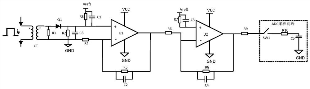
[0035] Please refer to figure 1 , an embodiment of the present invention provides a pulse current sampling circuit based on CT sampling, including a CT sampling circuit and a signal conditioning circuit; wherein,

[0036] The CT sampling circuit includes a current transformer CT, a first resistor R1, a second resistor R2, a diode Q1 and a sixth capaci...


PUM


Abstract

The invention discloses a pulse current sampling circuit based on CT sampling. The pulse current sampling circuit comprises a CT sampling circuit and a signal conditioning circuit. The CT sampling circuit comprises a current transformer CT, a first resistor R1, a second resistor R2, a diode Q1 and a sixth capacitor C6; the signal conditioning circuit comprises a first operational amplifier U1, a second operational amplifier C2, a third resistor R3, a fourth resistor R4, a fifth resistor R5, a sixth resistor R6, a seventh resistor R7, an eighth resistor R8, a ninth resistor R9, a first capacitor C1, a second capacitor C2, a third capacitor C3 and a fourth capacitor C4. The narrow pulse current sampling accuracy is improved with low device cost, the common-mode interference voltage of the sampling signal is reduced, the sampling bandwidth of the sampling conditioning loop is optimized, and the circuit has good application value.

Description

technical field [0001] The invention relates to the technical field of power electronics, in particular to a pulse current sampling circuit based on CT sampling. Background technique [0002] In power electronic systems, CT (Current Transformer, current transformer) is a device that converts a large current on the primary side into a small current on the secondary side based on the principle of electromagnetic induction. It is characterized by low cost, high precision, and fast response. , are becoming more and more popular. [0003] At present, since the CT needs to be magnetically reset, it is more suitable for the sampling of pulse signals. In some special applications or special working conditions, there are hundreds of nanosecond-level narrow pulse voltages or currents in the power electronic circuit system, and the commonly used sampling and conditioning circuits have slow response and low accuracy for the accuracy of hundreds of nanosecond-level narrow pulse current ...

Claims


Application Information

Patent Timeline
Patent Type & Authority Applications(China)
IPC IPC(8): G01R19/00
CPCG01R19/00
Inventor 杨勇李现亭张斌刘国栋朱路
Owner 易事特储能科技有限公司
Features
  • R&D
  • Intellectual Property
  • Life Sciences
  • Materials
  • Tech Scout
  • Unparalleled Data Quality
  • Higher Quality Content
  • 60% Fewer Hallucinations
Learn More