
Self-focusing imaging method and system for circular synthetic aperture radar, and electronic equipment

A technology of synthetic aperture radar and imaging method, which is applied in radio wave measurement system, radio wave reflection/re-radiation, utilization of re-radiation, etc. It can solve the problems of ignoring envelope error compensation, the influence of self-focusing BP effect, and high cost. , to achieve the effect of improving the accuracy

Active Publication Date: 2021-07-23
AEROSPACE INFORMATION RES INST CAS
View PDF8 Cites 2 Cited by
  • Summary
  • Abstract
  • Description
  • Claims
  • Application Information

AI Technical Summary

Problems solved by technology

At present, the airborne GPS and inertial navigation system and open source DEM data are difficult to self-focus to meet the high-band circular SAR imaging requirements, so it is necessary to use self-focusing algorithm imaging
[0004] In the existing self-focusing BP imaging algorithm, only the phase error caused by the motion error is estimated and compensated, and the compensation for the envelope error is ignored, which will lead to inaccurate compensation. In addition, the spatial variability of the phase error will also affect the The self-focusing BP effect has an impact, which makes the SAR image focusing effect not ideal
At the same time, the existing SAR image focusing process has a large overhead and requires relatively high computer memory

Method used


Image

  • Self-focusing imaging method and system for circular synthetic aperture radar, and electronic equipment
  • Self-focusing imaging method and system for circular synthetic aperture radar, and electronic equipment
  • Self-focusing imaging method and system for circular synthetic aperture radar, and electronic equipment

Examples


Embodiment Construction

[0048] In order to make the purpose, technical solutions and advantages of the embodiments of the present invention clearer, the technical solutions in the embodiments of the present invention will be clearly and completely described below in conjunction with the accompanying drawings in the embodiments of the present invention. Obviously, the described The embodiments are some of the embodiments of the present invention, but not all of them. Based on the embodiments of the present invention, all other embodiments obtained by persons of ordinary skill in the art without creative efforts fall within the protection scope of the present invention.

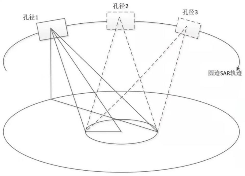
[0049] figure 1 A schematic diagram of SAR imaging provided by the embodiment of the present invention is shown. A circular SAR uses a small antenna as a single radiation unit to receive echo signals of the same ground object at different positions and perform related demodulation and compression processing. A small antenna (for exam...


PUM


Abstract

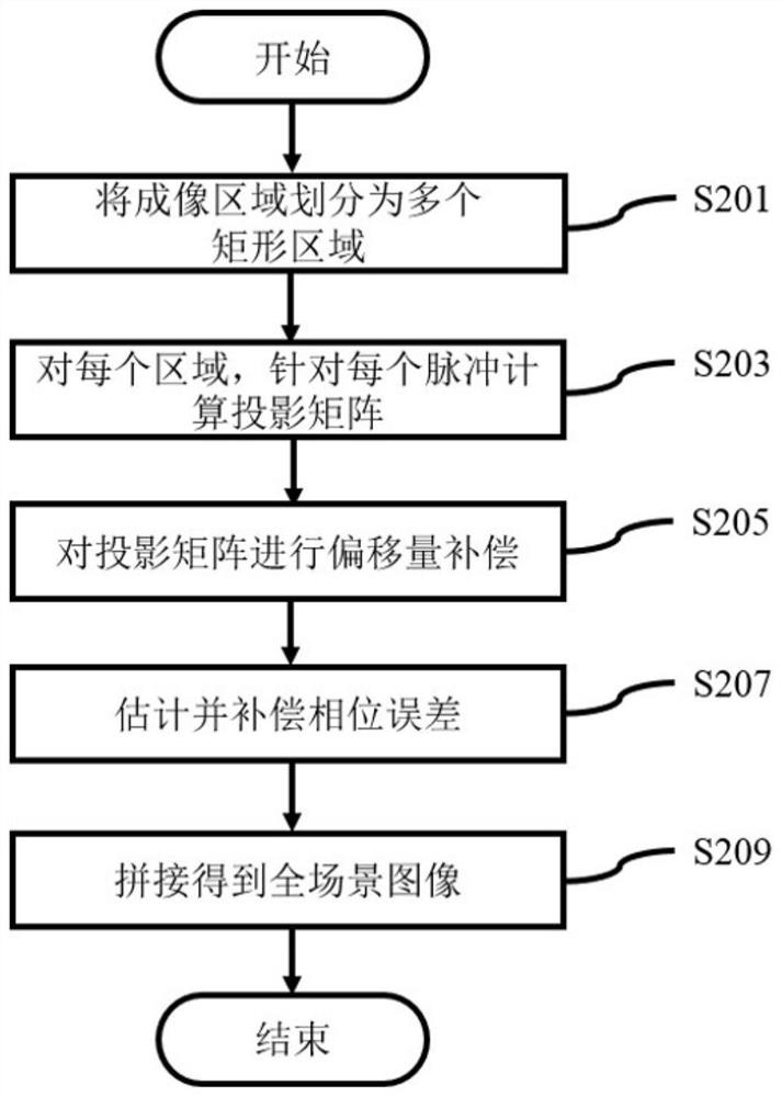
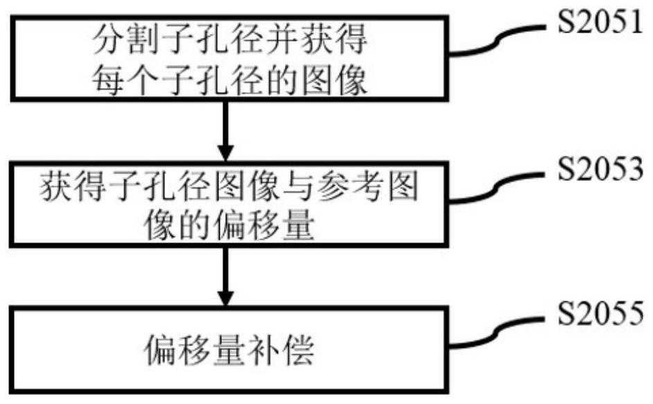
The embodiment of the invention provides a circular synthetic aperture radar self-focusing imaging method and system and electronic equipment. The method comprises the following steps: dividing an imaging region into a plurality of rectangular regions; for each of the plurality of rectangular regions, calculating a projection matrix for each pulse; performing image offset compensation on the projection matrix; performing phase error estimation and phase error compensation on the projection matrix after image offset compensation; and on the basis of the projection matrix after phase error compensation, obtaining a full-scene image of the imaging area through splicing. According to the invention, the envelope error and the phase error are compensated at the same time, the SAR imaging precision is improved, meanwhile, the imaging area is subjected to block processing, the influence of phase error space-variant characteristics on SAR imaging is reduced, and the requirement of SAR imaging for the storage space is lowered.

Description

technical field [0001] The invention relates to the technical field of radar imaging, in particular to a circular synthetic aperture radar self-focus imaging method, system and electronic equipment. Background technique [0002] Synthetic Aperture Radar (SAR) is a microwave active remote sensing device with all-weather and all-weather working characteristics, so it is widely used in military and civilian fields. In the traditional SAR working mode, the radar platform flies along a straight line and the synthetic aperture length is very limited, which causes common problems in SAR images such as overlapping, shadows, and perspective shortening. In order to solve these problems, a working mode of circular track SAR is proposed. [0003] Generally, the back projection algorithm (Back Projection, BP) is used to image the circular track SAR data, and the BP algorithm has high requirements on the accuracy of the terrain and the trajectory of the radar platform. At present, the a...

Claims


Application Information

Patent Timeline
IPC IPC(8): G01S13/90
CPCG01S13/9052G01S13/9021
Inventor 滕飞洪文
Owner AEROSPACE INFORMATION RES INST CAS
Learn More