
Three-dimensional gully volume change calculation method based on terrain point cloud

A technology of volume change and calculation method, applied in calculation, 3D image processing, instruments, etc., can solve the problem that the volume change of different surface point clouds cannot be effectively distinguished and expressed, the erosion and deposition characteristics cannot be effectively expressed, and the volume change of the study area Calculate errors and other problems, to reduce the filtering time and human intervention errors, improve the filtering accuracy, and achieve the effect of convenience

Active Publication Date: 2021-07-23
XIAN UNIV OF SCI & TECH
View PDF5 Cites 2 Cited by
  • Summary
  • Abstract
  • Description
  • Claims
  • Application Information

AI Technical Summary

Problems solved by technology

This leads to the inability to effectively distinguish and express the volume changes of different surface point clouds, which in turn leads to calculation errors in the volume changes of the study area;
[0005] Second, when the terrain is vertical or nearly vertical, the traditional two-dimensional method projects the terrain change point cloud to the grid for volume calculation, but the area of ​​the grid cannot represent the real surface area of ​​the terrain change, resulting in the volume of the study area calculation error;
[0006] Third, the projection of multiple terrain change point clouds to the same grid unit will ignore the specific information of different point cloud changes, so that erosion and deposition features cannot be effectively expressed in two-dimensional grids; and the vertical or approximately vertical surface changes before and after points Cloud subtraction results are difficult to correspond to erosion and deposition features

Method used


Image

  • Three-dimensional gully volume change calculation method based on terrain point cloud
  • Three-dimensional gully volume change calculation method based on terrain point cloud

Examples


Embodiment Construction

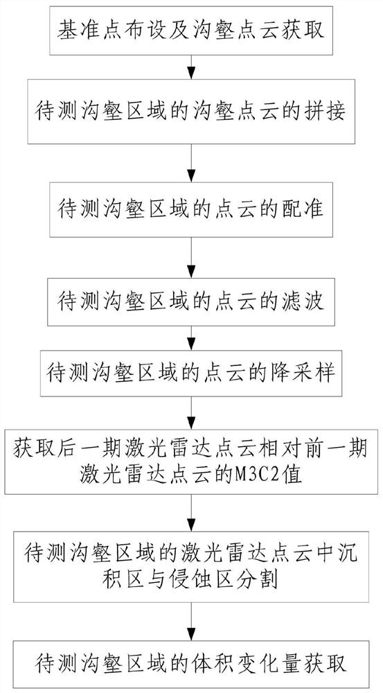
[0073] like figure 1 A three-dimensional calculation method based on a gully volume based on terrain point cloud, including the following steps:

[0074] Step 1, the reference point cloth and the gully point cloud acquisition:

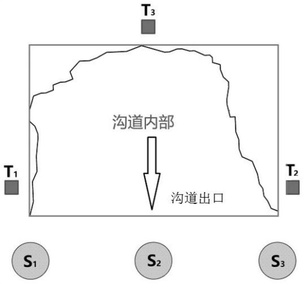
[0075] Step 101, the first reference point, the second base point, and the third base point, the first reference point, the second base and the third base point, respectively, respectively, in the first reference point, the second base and the third base point, respectively A standard ball, the second target ball, and the third standard ball, and acquires three-dimensional coordinates of the first target ball, the second target ball, and the third standard ball in the WGS-84 coordinate system; wherein Three-dimensional coordinate marker of a target ball 1 , Three-dimensional coordinate marker of the second target ball 2 , Three-dimensional sitting markers of the third standard ball for T 3 ;

[0076] Step 102, using the ground three-dimensional laser scann...


PUM


Abstract

The invention discloses a three-dimensional gully volume change calculation method based on terrain point cloud. The method comprises the following steps: 1, arranging reference points and acquiring gully point clouds; 2, splicing gully point clouds of a gully area to be measured; 3, registering point clouds of a gully area to be measured; 4, filtering the point cloud of the gully area to be measured; 5, down-sampling the point cloud of the gully area to be measured; 6, acquiring an M3C2 value of the laser point cloud of the latter stage relative to the laser point cloud of the former stage; 7, segmenting a deposition area and an erosion area in the laser point cloud of the gully area to be measured; and 8, obtaining the volume variation of the gully area to be measured. The method is simple in step, the volume variation of the sedimentary area and the volume variation of the erosion area in the to-be-measured gully area are obtained, so that the volume variation of the to-be-measured gully area is obtained, the accuracy of channel volume variation calculation based on the topographic change point cloud is improved, and the channel topography is adapted.

Description

Technical field [0001] The invention belongs to the field of gully volume change measurement, in particular, to a three-dimensional calculation method based on a gully volume change based on a terrain point cloud. Background technique [0002] In recent years, based on real-time dynamic carrier phase differential technology (RTK GPS), photographic measurement, interference radar (INSAR), laser radar (Lidar), the rapid and efficient monitoring of terrain changes is based on the rapid and efficient monitoring of terrain changes. High precision terrain monitoring is mostly used by terrain models or point clouds. Compared to the former, the direct contrast of point clouds avoids additional errors introduced when interpolation generates the terrain model, and therefore has higher precision, and the application in terrain changes is increasing. [0003] Topographic change monitoring method based on point cloud can obtain the acquisition of the topographic change to obtain a real terrai...

Claims


Application Information

Patent Timeline
IPC IPC(8): G06T15/00G06T17/05G06T19/20
CPCG06T15/00G06T17/05G06T19/20
Inventor 李朋飞高晨迪胡晋飞严露郝铭揆
Owner XIAN UNIV OF SCI & TECH
Learn More