

Device for measuring surface flow field of molten steel in crystallizer based on current change
A measuring device and a technology for current change, applied in the field of iron and steel metallurgy and steelmaking, can solve the problems of difficulty in measuring the change of the molten steel flow field of the mold, and achieve the effect of ensuring accuracy
- Summary
- Abstract
- Description
- Claims
- Application Information
AI Technical Summary
Problems solved by technology
Method used
Image

Examples
Embodiment 1
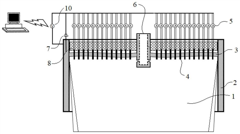
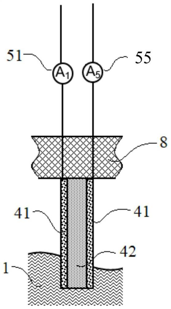
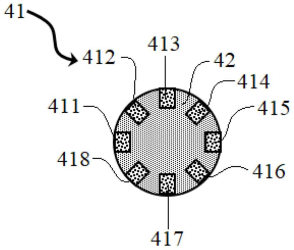
[0035] combine Figure 1~3, a device for measuring the surface flow field of molten steel in a crystallizer based on current changes in this embodiment includes a nail 4, an ammeter 5, a power supply 7, a nail fixing plate 8, and a voltmeter 10, and the nail 4 is vertically fixed As for the nail fixing plate 8, the nail 4 is in the shape of a cylinder, and the nail 4, the ammeter 5, the power supply 7 and the mold copper plate 2 are respectively connected in series by wires, and the voltmeter 10 is connected in parallel with the nail 4. This nail 4 is made up of resistance 41 and refractory material 42, and resistance 41 is distributed along the inner surface of refractory material 42 cylinder n equally, and the value of n in this embodiment is 8, and ammeter 5 is connected with resistance 41 through lead wire, and the ammeter of this embodiment 5 is composed of a first ammeter 51, a second ammeter 52, a third ammeter 53, a fourth ammeter 54, a fifth ammeter 55, a sixth ammete...
Embodiment 2
[0046] The basic content of this embodiment is the same as that of Embodiment 1. The difference is that the nail insert 4 also includes a heating element 43, which is cylindrical and arranged inside the cylinder of the nail insert 4. The heating element 43 is heated by a silicon molybdenum rod. or electromagnetic heating such as Figure 5 As shown, the heating temperature of the heating member 43 is consistent with the temperature of the molten steel 1 during use. The temperature field around the nail 4 changes sharply, resulting in a change in the flow field, and the original temperature field and flow field are kept unchanged to the greatest extent to achieve measurement accuracy.
[0047] The steps of the method for measuring the flow field change of molten steel 1 in the mold based on current changes in this embodiment are basically the same as in Example 1, except that the pretreatment step is added: the temperature of molten steel 1 in the mold is measured, The nail 4 i...
PUM
| Property | Measurement | Unit |
|---|---|---|
| Diameter | aaaaa | aaaaa |
| Heat resistance temperature | aaaaa | aaaaa |
Abstract
Description
Claims
Application Information