Volute and compressor
A technology for compressors and centrifugal compressors, applied in the field of compressors, can solve problems such as flow loss, and achieve the effects of reducing flow loss, increasing resistance, and preventing separation
- Summary
- Abstract
- Description
- Claims
- Application Information
AI Technical Summary
Problems solved by technology
Method used
Image

Examples
Embodiment Construction
[0025] The present invention will be further described below in conjunction with embodiment, but is not limited to the content on the description.
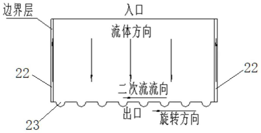
[0026] When the fluid passes through the surface, the speed will gradually decrease due to friction to form a boundary layer. When the boundary layer separates, a vortex will be formed, which will cause the fluid in the boundary layer to flow in reverse, reduce the co-flow area of the main channel, and cannot play the role of diffusion. At the same time, due to the speed difference between the airflows flowing in the volute, the inner wall of the fluid volute will generate a secondary flow perpendicular to the fluid direction, disturbing the flow field in the main flow area.
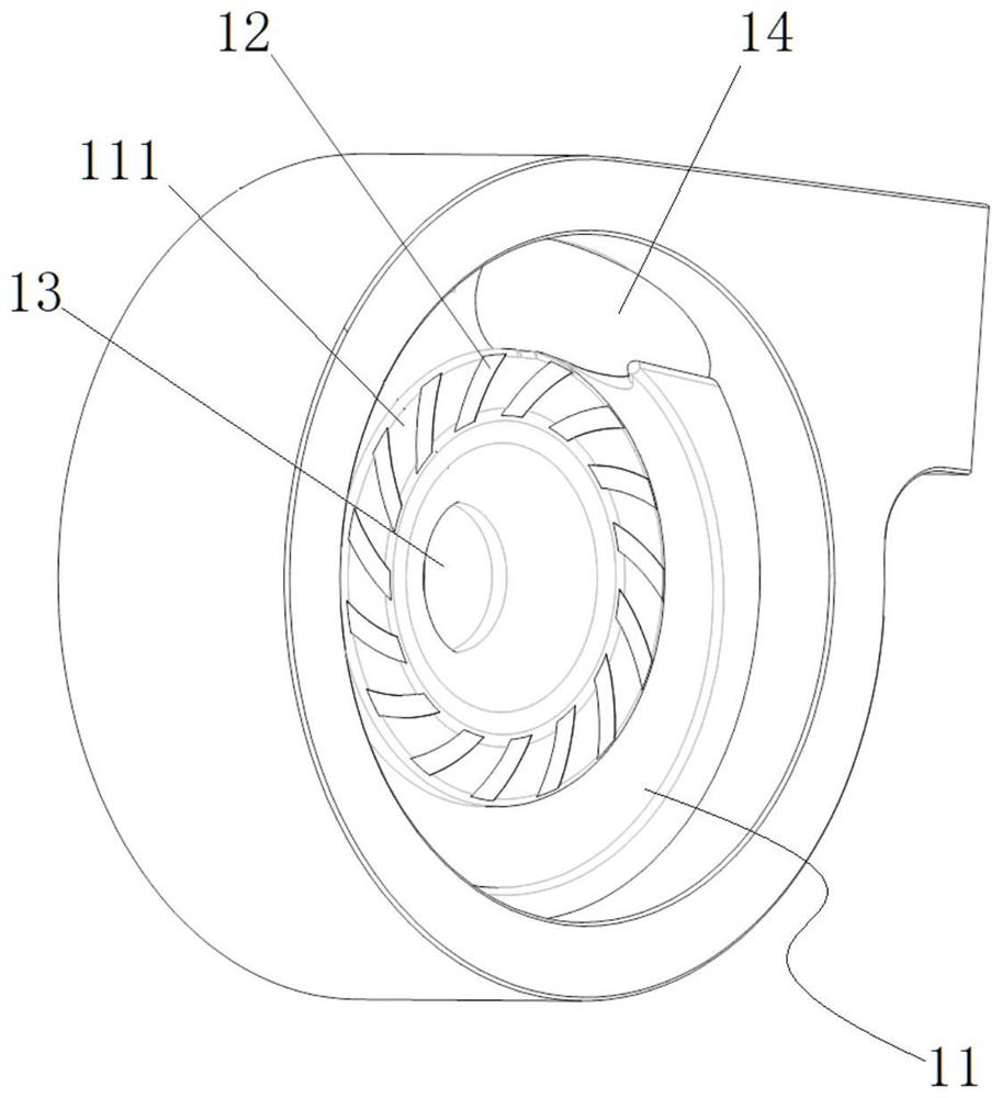
[0027] Such as figure 1 As shown, according to the first embodiment of the present invention, a volute is disclosed, the volute is used in a centrifugal compressor, the inner wall 11 of the volute is provided with a guide groove 12, and the guide groove 12...
PUM
 Abstract
Description
Claims
Application Information
PatSnap Eureka turns technology decisions into work you can execute. Powered by our Innovation Knowledge Graph, it runs expert workflows across engineering, life sciences, materials and intellectual property. Get your review-ready output in minutes.


