
Medical air conditioning device

An air-conditioning device and medical technology, applied in air-conditioning systems, heating devices, applications, etc., can solve the problems of high noise of the working medium of the draft tube assembly, and achieve the effects of alleviating excessive pressure concentration, reducing noise, and improving heat exchange efficiency

Active Publication Date: 2021-07-27
SINODEU MEDICAL CO LTD
View PDF5 Cites 0 Cited by
  • Summary
  • Abstract
  • Description
  • Claims
  • Application Information

AI Technical Summary

Problems solved by technology

In the prior art, the working fluid noise of the draft pipe assembly in the air conditioning device is relatively large

Method used


Image

  • Medical air conditioning device
  • Medical air conditioning device
  • Medical air conditioning device

Examples


Embodiment 1

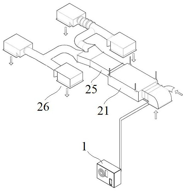
[0031] Embodiment 1: A medical air-conditioning device, including an indoor cooling module 21 and an outdoor heat exchange module 1 communicated through pipelines, and a fan 22, a refrigeration module 23 and at least two a filter 24;

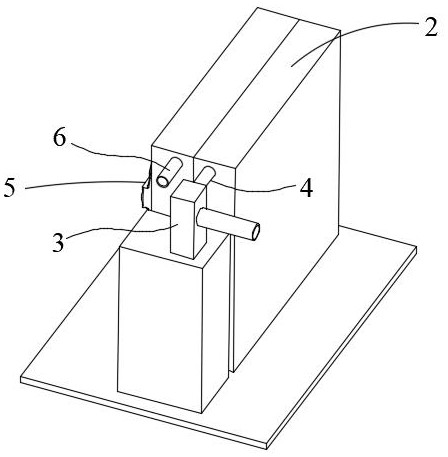
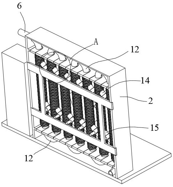
[0032] The outdoor heat exchange module 1 includes a housing 2, a pump body 3, a front guide tube assembly 5 with a liquid inlet pipe 4 at one end, and a rear guide tube assembly 7 with a liquid outlet pipe 6 at one end, located at the front The other ends below the flow tube assembly 5 and the rear guide tube assembly 7 communicate through an intermediate tube 8, and the liquid inlet pipe 4 and the liquid outlet pipe 6 are respectively located at the front guide tube assembly 5 and the rear guide tube assembly 7 respectively. above, the pump body 3 is connected to the front guide tube assembly 5 or the rear guide tube assembly 7;

[0033] Both the front guide tube assembly 5 and the rear guide tube assembly 7 are composed of several heat excha...

Embodiment 2

[0036] Embodiment 2: A medical air-conditioning device, including an indoor cooling module 21 and an outdoor heat exchange module 1 communicated through pipelines, and a fan 22, a refrigeration module 23 and at least two a filter 24;

[0037] The outdoor heat exchange module 1 includes a housing 2, a pump body 3, a front guide tube assembly 5 with a liquid inlet pipe 4 at one end, and a rear guide tube assembly 7 with a liquid outlet pipe 6 at one end, located at the front The other ends below the flow tube assembly 5 and the rear guide tube assembly 7 communicate through an intermediate tube 8, and the liquid inlet pipe 4 and the liquid outlet pipe 6 are respectively located at the front guide tube assembly 5 and the rear guide tube assembly 7 respectively. above, the pump body 3 is connected to the front guide tube assembly 5 or the rear guide tube assembly 7;

[0038] Both the front guide tube assembly 5 and the rear guide tube assembly 7 are composed of several heat excha...


PUM


Abstract

The invention discloses a medical air conditioning device which comprises an indoor cooling module and an outdoor heat exchange module which are communicated through a pipeline; the outdoor heat exchange module comprises a shell, a pump body, a front flow guide pipe assembly with a liquid inlet pipe at one end and a rear flow guide pipe assembly with a liquid outlet pipe at one end; the other ends located below the front flow guide pipe assembly and the rear flow guide pipe assembly are communicated through a middle pipe, the liquid inlet pipe and the liquid outlet pipe are located above the front flow guide pipe assembly and the rear flow guide pipe assembly respectively, the head ends and the tail ends of adjacent heat exchange flow guide pipes are communicated through bent pipes, and cooling fins are arranged on the outer sides of the heat exchange flow guide pipes; and first communicating pipes and second communicating pipes are obliquely arranged between the upper portions and between the lower portions of the adjacent heat exchange flow guide pipes in the front flow guide pipe assembly or the rear flow guide pipe assembly which are located on the same side with the pump body and connected with the pump body. According to the medical air conditioning device, the uniformity of heat distribution is improved, and the heat resistance is reduced, so that the overall heat exchange efficiency of the flow guide pipes and the cooling fins is improved.

Description

technical field [0001] The technical field of the medical air conditioner of the present invention particularly relates to a medical air conditioner. Background technique [0002] Medical purification air-conditioning equipment is to arrange the air supply outlet and return air outlet reasonably in the medical air-conditioning room, so that the air that has been purified and heat-humidified is sent into the room through the air supply outlet, and is evenly eliminated in the process of diffusion and mixing. Indoor residual heat and residual humidity, so that the working area forms a relatively uniform and stable temperature, humidity, air velocity and cleanliness to meet the requirements of production technology and human comfort. [0003] The heat exchanger component in the air conditioning system is an important component, which exists in almost all air-cooled air conditioning systems. Its main function is to exchange heat between the air conditioning refrigerant and the ex...

Claims


Application Information

Patent Timeline
Patent Type & Authority Applications(China)
IPC IPC(8): F24F1/0003F24F1/0073F24F1/16F24F1/18F24F13/24
CPCF24F13/24F24F2013/247F24F13/28F24F3/00F24F13/30
Inventor 樊磊冯平杨娜娜
Owner SINODEU MEDICAL CO LTD
Learn More