
Camera and galvanometer combined variable sight line system three-dimensional imaging model and calibration method thereof

A three-dimensional imaging and line-of-sight technology, applied in biological neural network models, measuring devices, instruments, etc., can solve problems such as difficult three-dimensional vision applications and complex three-dimensional imaging models, achieving high universality, broad application prospects, and strong reliability. Effect

Active Publication Date: 2021-07-27
NANJING UNIV OF AERONAUTICS & ASTRONAUTICS
View PDF5 Cites 5 Cited by
  • Summary
  • Abstract
  • Description
  • Claims
  • Application Information

AI Technical Summary

Problems solved by technology

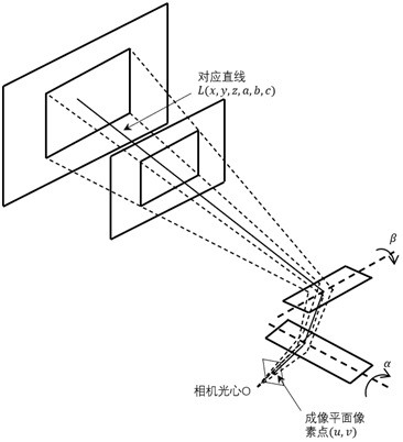
Therefore, the imaging position of the 3D scene on the imaging plane is not only related to the 3D scene and the imaging parameters of the camera itself including nonlinear distortion, but also has a complicated relationship with the two deflection angles of the galvanometer. These factors are combined to make The 3D imaging model of the camera-galvanometer imaging system is very complex, so no one has proposed a 3D imaging model of the camera-galvanometer variable line-of-sight imaging system, and the camera-galvanometer imaging system is currently difficult to be directly used in 3D vision that requires quantitative geometric relationships. in application

Method used


Image

  • Camera and galvanometer combined variable sight line system three-dimensional imaging model and calibration method thereof
  • Camera and galvanometer combined variable sight line system three-dimensional imaging model and calibration method thereof
  • Camera and galvanometer combined variable sight line system three-dimensional imaging model and calibration method thereof

Examples


Embodiment Construction

[0042] The present invention is described in further detail now in conjunction with accompanying drawing.

[0043] It should be noted that terms such as "upper", "lower", "left", "right", "front", and "rear" quoted in the invention are only for clarity of description, not for Limiting the practicable scope of the present invention, and the change or adjustment of the relative relationship shall also be regarded as the practicable scope of the present invention without substantive changes in the technical content. The two-dimensional vibrating mirror in the present invention usually contains two optical total reflection mirrors, and a deflecting mirror can also be used to deflect around two axes during specific implementation. Without substantive changes in the technical content, it should also be regarded as the present invention. practicable scope.

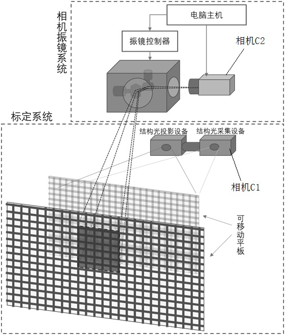
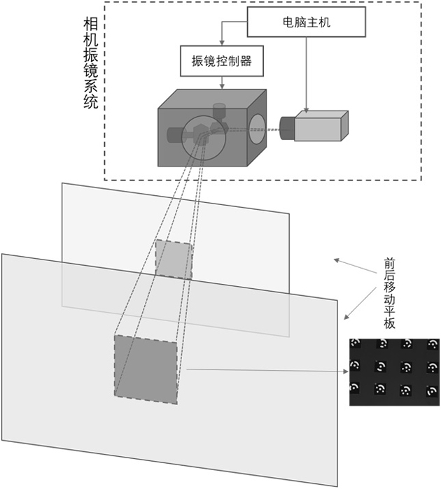
[0044] as attached Figure 1-3 As shown, a camera-galvanometer combined variable line of sight imaging system disclosed in th...


PUM


Abstract

The invention discloses a camera and galvanometer combined variable sight line system three-dimensional imaging model and a calibration method thereof. Hardware of a variable sight line imaging system comprises a computer, a two-dimensional galvanometer, a CCD or CMOS area-array camera and a group of optical lenses. The two-dimensional galvanometer comprises two optical total reflection mirrors, and the two optical total reflection mirrors can rapidly deflect around an axis under the control of a computer signal, so that the sight line direction and the corresponding imaging area of an image sensor composed of the camera and the lens are changed. According to the three-dimensional imaging model of the variable sight line imaging system, a mapping relation among pixel positions on an image plane, two angle control quantities of a two-dimensional galvanometer and spatial incident light is established. The invention further discloses a calibration method of the variable sight line imaging system three-dimensional imaging model. The model has the outstanding advantage that the camera and galvanometer combined variable sight line imaging systemcan meet the requirements of large-view-field three-dimensional vision application.

Description

technical field [0001] The invention belongs to the technical field of machine vision, and in particular relates to a three-dimensional imaging model of a variable line of sight system combined with a camera and a vibrating mirror and a calibration method thereof. Background technique [0002] The two-dimensional vibrating mirror is a vector scanning device that is driven by two special swing motors to quickly deflect two optical lenses around their respective rotation axes. With the continuous development of two-dimensional galvanometer manufacturing technology, the positioning accuracy, repeatability and scanning speed of the galvanometer have been greatly improved, and it has been widely used in many fields. For example, changing the outgoing direction of the incident laser beam through the high-speed axial deflection of two optical lenses has been widely used in laser marking, laser processing, laser marking, laser medical beauty and other work. In recent years, two-dim...

Claims


Application Information

Patent Timeline
IPC IPC(8): G01B11/25G06N3/04
CPCG01B11/2545G06N3/04
Inventor 韩子东张丽艳
Owner NANJING UNIV OF AERONAUTICS & ASTRONAUTICS
Learn More