

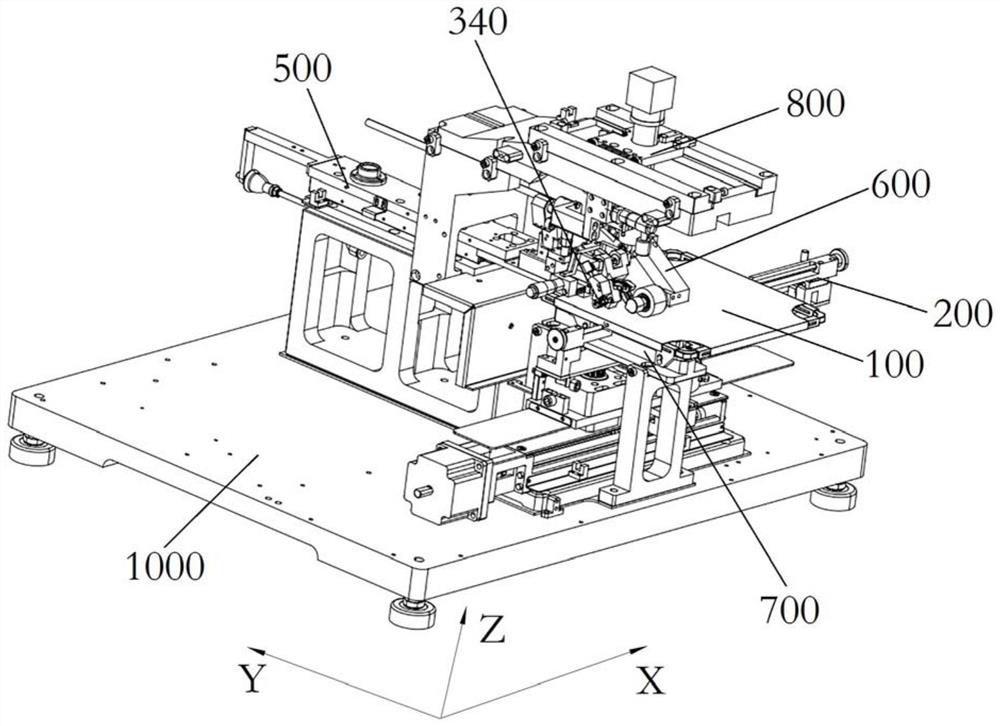
Chip cleavage equipment
A chip and equipment technology, applied in the field of chip cleavage equipment, can solve the problems of inaccurate positioning and low precision of lobes, and achieve the effect of high position adjustment accuracy, high precision, and ensuring accuracy and stability
- Summary
- Abstract
- Description
- Claims
- Application Information
AI Technical Summary
Problems solved by technology
Method used
Image

Examples
Embodiment 1
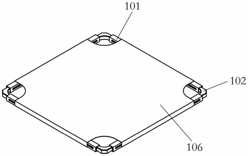
[0099] Such as figure 2 As shown, the stretch film holder 100 is rectangular and has four stretch film tubes 101, the four stretch film tubes 101 constitute the four sides of the stretch film stand 100, and the stretch film tube 101 has a cavity inside;
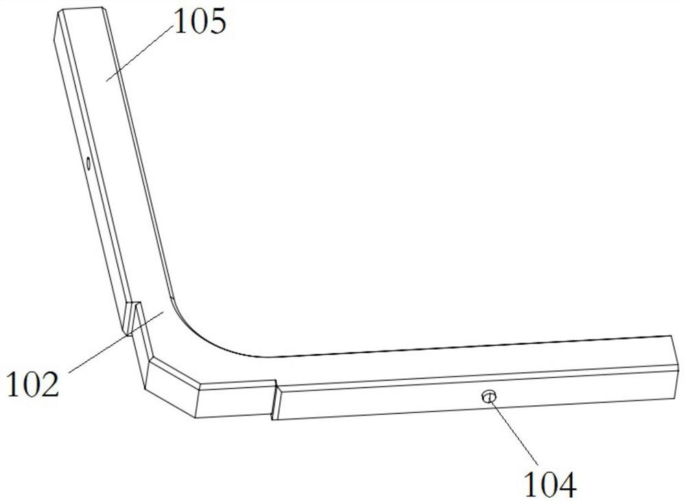
[0100] Such as image 3 As shown, the adjacent ends of two adjacent stretch film tubes 101 are slidably inserted with a tension angle 102. The tension angle 102 is "L" shaped, and the two ends are suitable for sliding insertion into the stretch film tubes. insertion end 105 within the cavity of 101;
[0101] Such as Figure 4 , 5 As shown, a limit device is set between the tension angle 102 and the stretch film tube 101; the limit device includes a limit groove 103 arranged on the side wall of the stretch film tube 101, and on the tension angle 102 and the limit The slot 103 cooperates with the positioning protrusion 104;
[0102] The specific structure can be that a through hole is provided at the insertion end 105 of ...
Embodiment 2
[0107] A scribing head device 340 provided in this embodiment, such as Figure 7 As shown, the fixed seat 301 is included, and the fixed seat 301 is fixed on the chip cleavage equipment. The fixed seat 301 is provided with a scribing knife through the position control structure 300 and the pressure control structure 400. The scribing knife has a tip for scribing. It is used for dicing on the wafer to facilitate subsequent cleavage.
[0108] Such as Figure 8 As shown, the position control structure 300 includes a first base 302, and the first base 302 is slidably arranged on a fixed base 301 through a sliding platform; on the fixed base 301, an adjustment knob 303 is provided for horizontal rotation, and the adjustment knob 303 has a direction toward the the protruding abutment end of the first base 302;
[0109] Such as Figure 9 As shown, a mounting groove 304 is provided at the bottom of the fixing seat 301, and a third elastic member 305 is installed in the installing g...
Embodiment 3
[0126] The present embodiment provides the split head device 600 for chip 619 cleavage, which is arranged on the chip 619 cleavage equipment; as Figure 18 As shown, it includes: a second base 601, a lifting arm 603 and a driving rod 607; the roller 611 on the lifting arm 603 is pressed on the chip 619 with a scribe line, and the driving device drives the lifting arm 603 to rotate to realize the lifting arm 603 A force is provided to make the roller 611 press down, so that the chip 619 is cracked along the scribe line.
[0127] Such as Figure 19 , 20 As shown, the front end of the second base 601 is provided with a "U"-shaped opening, and a rotating shaft 602 is rotated in the opening, and a lifting arm 603 is sleeved and connected to the rotating shaft 602, so as to realize the rotating connection between the lifting arm 603 and the second base 601;
[0128] Such as Figure 21 , 22 As shown, an abutment plate 604 is provided at one end of the lifting arm 603 close to the...
PUM
 Abstract
Description
Claims
Application Information