Surface dust sticking equipment for PCB production

A PCB board and dust-sticking technology, applied in cleaning methods and utensils, chemical instruments and methods, etc., can solve problems such as inflexible operation, time-consuming and labor-intensive, and low efficiency

Active Publication Date: 2021-07-30
江西威尔高电子股份有限公司
View PDF17 Cites 1 Cited by
  • Summary
  • Abstract
  • Description
  • Claims
  • Application Information

AI Technical Summary

Problems solved by technology

[0004] In order to overcome the shortcomings of inflexible operation, time-consuming and labor-intensive operation, and frequent replacement of sticky paper after long-term use, resulting in low efficiency, the technical problem of the present...

Method used


Image

  • Surface dust sticking equipment for PCB production
  • Surface dust sticking equipment for PCB production
  • Surface dust sticking equipment for PCB production

Examples


Embodiment 1

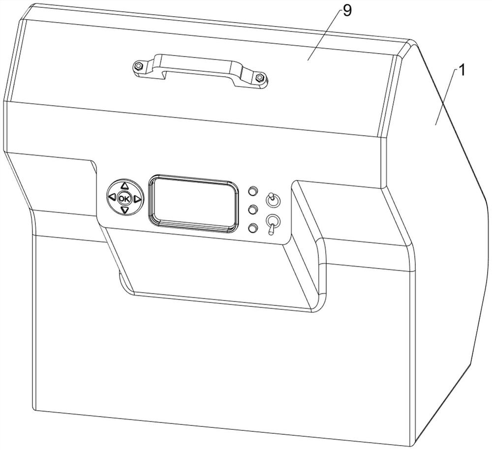
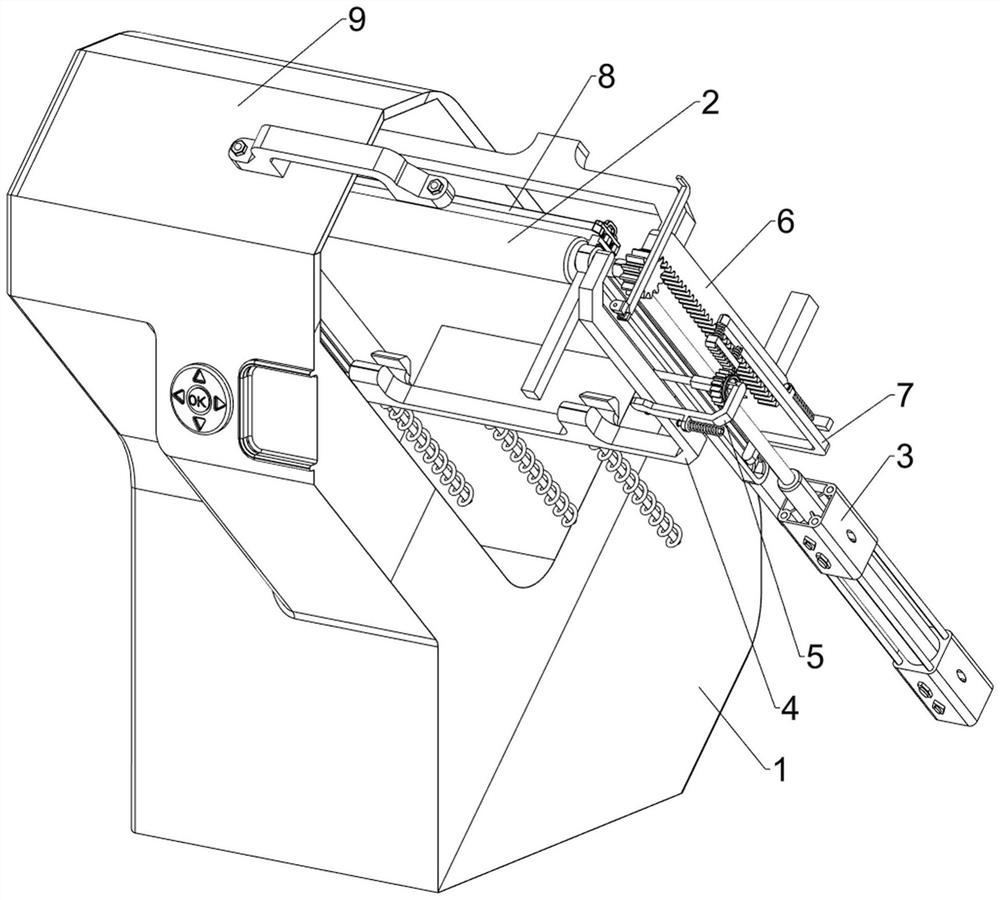
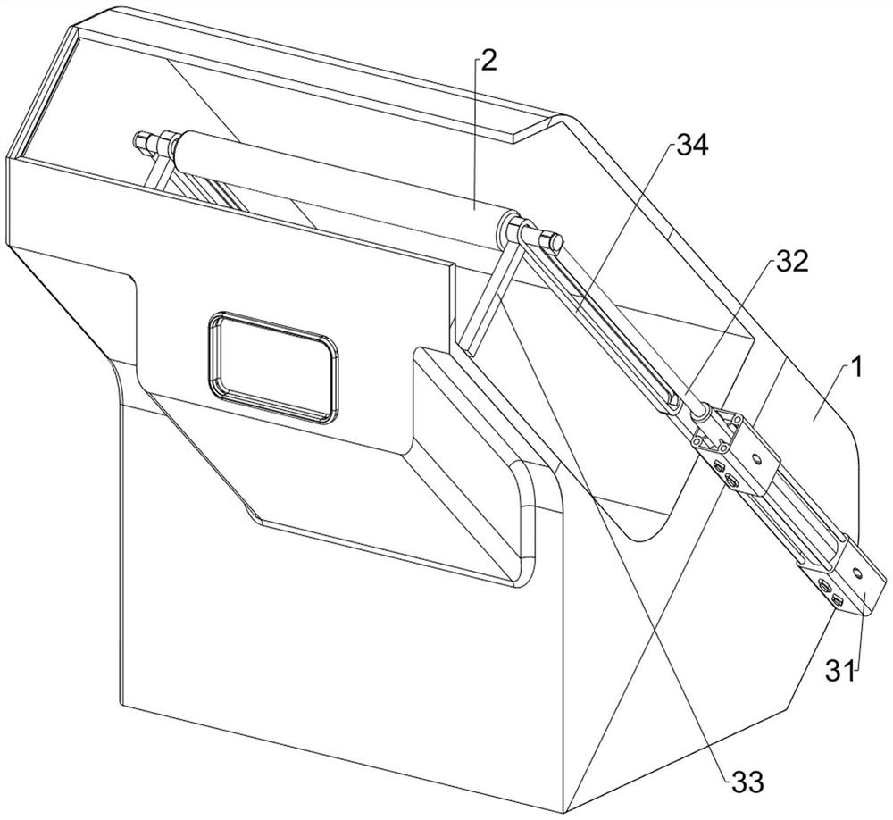
[0030] A kind of surface sticking dust equipment for PCB board production, such as Figure 1-Figure 5 As shown, it includes a casing 1, a sticky glue stick 2, a moving component 3, a placement component 4 and a clamping component 5, a moving component 3 is arranged inside the casing 1, and a sticky sticky glue stick 2 is arranged on the moving component 3 in a rotating manner. The moving component 3 is provided with a placing component 4 , and the placing component 4 is provided with a clamping component 5 .

[0031] First, people put the PCB board into the placement component 4 in the shell 1, start the moving component 3 to drive the sticky glue stick 2 to move downward, and at the same time, the moving component 3 cooperates with the clamping component 5, and the clamping component 5 clamps the PCB board. The dust-sticking glue stick 2 moves downward under the action of the moving component 3 to carry out the dust-sticking work on the PCB board, so as to achieve the effect ...

Embodiment 2

[0037] On the basis of Example 1, such as Figure 6-Figure 11 As shown, a rotating assembly 6 is also included. The rotating assembly 6 includes a second support rod 61, a spur rack 62 and a spur gear 63. The upper rear side of the housing 1 is provided with a second support rod 61. The front of the second support rod 61 Side left and right symmetry is provided with spur rack 62, sticky dust glue stick 2 is provided with spur gear 63 left and right symmetry, and spur gear 63 meshes with spur rack 62.

[0038] In order to prevent the sticky rubber stick 2 from rotating inflexibly on the push rod 32, when the cylinder 31 is activated and the push rod 32 and the sticky sticky stick 2 move downward, the spur gear 63 on the sticky stick 2 is driven to move downward. , under the action of the spur rack 62, the spur gear 63 and the sticky stick 2 automatically rotate to improve the effect of sticking dust on the surface of the PCB. When the cylinder 31 is closed, the push rod 32, the...


PUM


Abstract

The invention relates to dust sticking equipment, in particular to surface dust sticking equipment for PCB production. to the technical problem is to provide the surface dust sticking equipment for PCB production which can optimize automation, save manpower, improve the surface dust sticking effect, and improve the working efficiency. According to the technical scheme, the surface dust sticking equipment for PCB production comprises a shell, a moving assembly, a dust sticking rubber roller, a placing assembly and a clamping assembly; the moving assembly is arranged in the shell; the dust sticking rubber roller is rotationally arranged on the moving assembly; the placing assembly is arranged on the moving assembly; and the clamping assembly is arranged on the placing assembly. According to the equipment, a PCB is placed in the placing assembly in the shell by people, the moving assembly is started to drive the dust sticking rubber roller to move downwards, meanwhile, the moving assembly is matched with the clamping assembly, the clamping assembly clamps the PCB, the dust sticking rubber roller moves downwards under the action of the moving assembly, dust sticking work is carried out on the PCB, and the effects of optimizing automation and saving manpower are achieved.

Description

technical field [0001] The invention relates to a dust sticking device, in particular to a surface dust sticking device for PCB board production. Background technique [0002] The PCB board is the carrier for the electrical connection of electronic components. In the process of changing the PCB board from an ordinary copper board to a product with specific functions, its surface is covered with a dry film, and the surface of the dry film is protected by a film. The protective film needs to be removed when using it. The photosensitive material is exposed, and the dry film after tearing off the protective film has a certain amount of static electricity, which is extremely easy to adhere to garbage and cause a short circuit. Clean up. In the process of PCB board processing, the traditional dust sticking device is directly fixed on the frame, and the position of the dust sticking device does not change. When the thickness of the PCB board is different, it needs to be reinstalle...

Claims


Application Information

Patent Timeline
IPC IPC(8): B08B7/00B08B13/00
CPCB08B7/0028B08B13/00
Inventor 贾晓燕陈晓东
Owner 江西威尔高电子股份有限公司
Why Eureka
Try Eureka