
Mounting equipment for magnets in electronic cigarette atomizer

An electronic cigarette atomizer and installation equipment technology, applied in metal processing equipment, tobacco, transportation and packaging, etc., can solve problems such as low production efficiency, long time consumption, and inability to meet industrial production needs.

Inactive Publication Date: 2021-07-30
SHENZHEN AIRUISI ELECTRONICS CO LTD
View PDF0 Cites 0 Cited by
  • Summary
  • Abstract
  • Description
  • Claims
  • Application Information

AI Technical Summary

Problems solved by technology

[0004] In order to overcome the traditional installation of magnets inside the atomizer is generally done manually, the user first fixes the atomizer, and at the same time the user installs the magnet inside the atomizer. In the case of a large number of atomizers Under the circumstances, the user needs to spend a long time to complete the installation of the magnet, the production efficiency is low, and the disadvantages that cannot meet the needs of industrial production. Material electronic vaporizer internal magnet installation device

Method used


Image

  • Mounting equipment for magnets in electronic cigarette atomizer
  • Mounting equipment for magnets in electronic cigarette atomizer
  • Mounting equipment for magnets in electronic cigarette atomizer

Examples


Embodiment 1

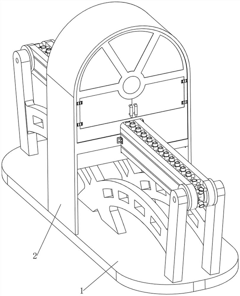
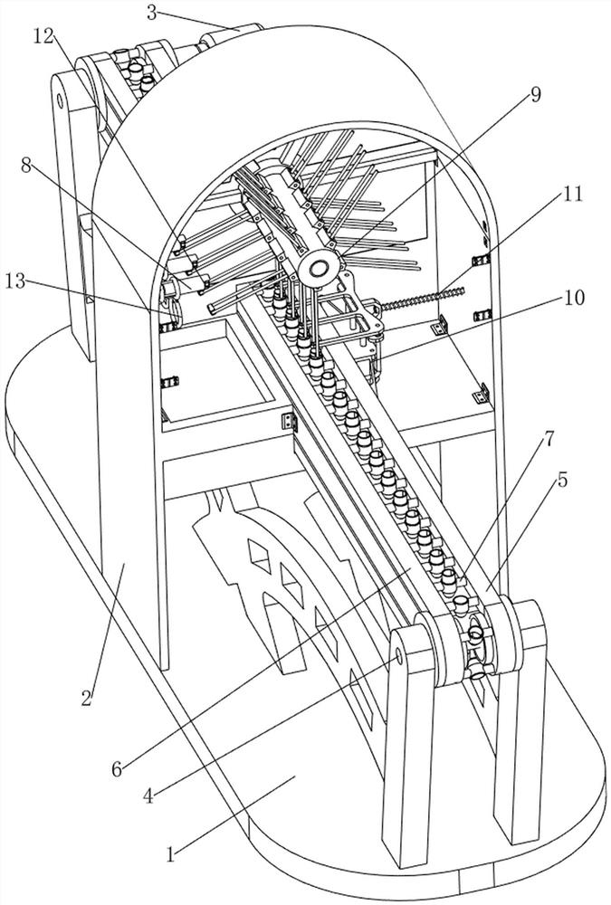
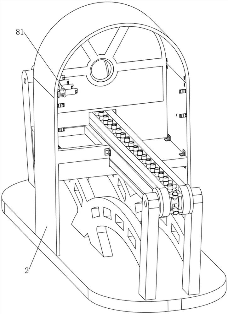
[0072] Electronic smoke inside magnet mounting equipment, such as Figure 1-8 As shown, including the base 1, the main frame 2, the first motor 3, the first rotating shaft 4, the first pulley assembly 5, the second pulley assembly 6, the material tower tower 7, the discharge mechanism 8, and the rotating discharge mechanism 9, The main frame 2 is disposed on the upper side of the base 1, and the upper right rear side of the base 1 is mounted with a first motor 3. The upper and rear side of the base 1 is rotatable, and the first axis 4 is provided with the first axle 4, the first axis 4 and the first The output shaft of the motor 3 is connected between the two first shafts 4, and the first leather wheel assembly 5 is composed of two first pulley and the first belt, a first pulley connected to the rear side. On the right side of the first shaft 4, the other first pulley is connected to the right side of the first axis 4 on the front side, and the first leather belt is between the two...

Embodiment 2

[0079] On the basis of Example 1, such as figure 2 and Figure 9-18 The pressing mechanism 10 includes a pressing mechanism 10 including a fixed frame 101, a cylinder 102, a second fixing lever 103, a first pressure plate 104, a third spring 105, and a second pressure plate 106, and the upper right side of the upper portion of the base 1. Both sides are provided with a fixed frame 101, and the two fixed frames 101 are connected between the two fixed frames 101, and the second fixing rod 103 is provided in the upper portion of the two fixed frame 101, and the lower portion of the two second fixed rods 103 is slidable. There is a first pressure plate 104, the first pressure plate 104 is connected to the telescopic rod of the cylinder 102, and the second pressure plate 106 is slidably connected between the two second fixed rods 103, and the second pressure plate 106 is connected between the first pressure plate 104. Two third spring 105.

[0080] When the pressing mechanism 10 is used...


PUM


Abstract

The invention relates to mounting equipment, in particular to mounting equipment for magnets in an electronic cigarette atomizer. The invention provides the mounting equipment for the magnets in the electronic cigarette atomizer. The mounting equipment automatically discharge, is quick to mount and facilitates feeding. The mounting equipment for the magnets in the electronic cigarette atomizer comprises a base, a main frame and a first motor, wherein the main frame is arranged at the middle side of the upper portion of the base; and the first motor is installed at the upper portion of the base. According to the mounting equipment, a discharging mechanism is arranged, the discharging mechanism is matched with a rotary emptying mechanism, the discharging mechanism in a compressed state resets to push other magnets to move rightwards, and the other magnets move rightwards so that the other magnets can be clamped by the rotary emptying mechanism next time; and the rotary emptying mechanism continues to rotate to drive the magnets to rotate to the position over a shell of the electronic cigarette atomizer, then a user pushes the magnets downwards, and the magnets can fall into the shell of the electronic cigarette atomizer, so that the work of installing the magnets in the electronic cigarette atomizer is achieved.

Description

Technical field [0001] The present invention relates to a mounting apparatus, and more particularly to an internal magnet mounting apparatus for an electronic smoke. Background technique [0002] Electronic smoke is an electronic product that mimics the cigarette, which is generally composed of a suction, atomizer and battery assembly. As consumer living standards continue to increase, with consumers have increased their quality of life and health care awareness, The majority of consumers reduce the damage to human health in order to quit smoking or minimize smoking, and use electronic smokeware to replace cigarettes, and the inside of the traditional nebulator is generally manually completed. Users first put electronic smoke units Fixed, while the user installs the magnet inside the electronic smoke, when the number of electronic smoke enumeors is large, the user needs to consume a long time to complete the mounting of the magnet, the production efficiency is low, and the indust...

Claims


Application Information

Patent Timeline
Patent Type & Authority Applications(China)
IPC IPC(8): B65G15/12B65G23/04B65G23/22B65G47/82A24F40/70B23P19/00
CPCA24F40/70B23P19/001B65G15/12B65G23/04B65G23/22B65G47/82
Inventor 周秀丽龙庆芳叶冠廉
Owner SHENZHEN AIRUISI ELECTRONICS CO LTD
Learn More