
A Waste Heat Recovery System Based on Gas Generating Set

A technology of waste heat recovery system and generator set, which is applied in the direction of water/sewage multi-stage treatment, special treatment targets, chemical instruments and methods, etc., which can solve problems such as blockage and great harm to human body, and achieve the effect of convenient disassembly and installation

Active Publication Date: 2021-10-22
GUANGZHOU LIYANG ENERGY TECH CO LTD
View PDF0 Cites 0 Cited by
  • Summary
  • Abstract
  • Description
  • Claims
  • Application Information

AI Technical Summary

Problems solved by technology

[0003] A certain amount of hot water will be generated after burning gas to generate electricity, which is usually reused to reduce energy waste. In reality, the generated hot water is usually passed into an incubator, and then transported to domestic hot water through a delivery device. Because the water produced after gas combustion contains more impurities, long-term accumulation will cause more scale to remain inside the incubator or in the connecting pipe between the micro-combustion body and the incubator, which will seriously cause blockage and harm the human body more sexual

Method used


Image

  • A Waste Heat Recovery System Based on Gas Generating Set
  • A Waste Heat Recovery System Based on Gas Generating Set
  • A Waste Heat Recovery System Based on Gas Generating Set

Examples


Embodiment Construction

[0036] The present invention will be further described below in conjunction with the accompanying drawings and embodiments.

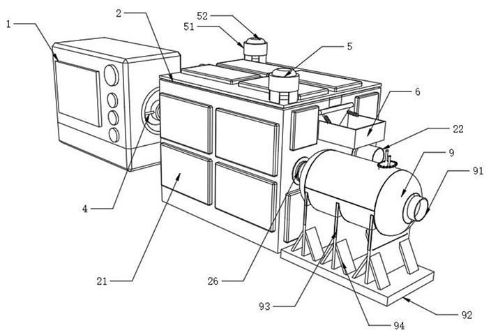
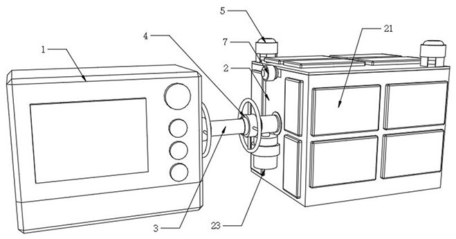
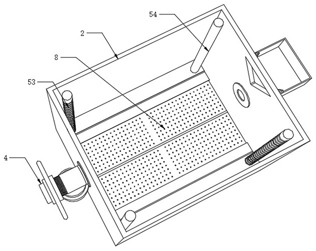
[0037] Please refer to figure 1 , figure 2 , image 3 , Figure 4 , Figure 5 , Figure 6 , Figure 7 , Figure 8 , Figure 9 and Figure 10 ,in, figure 1 One of the overall structural schematic diagrams provided by the present invention; figure 2 The second schematic diagram of the overall structure provided for the present invention; image 3 A schematic diagram of the internal structure of the incubator provided by the present invention; Figure 4 Schematic diagram of the structure of the filter mechanism provided by the present invention; Figure 5 Structural schematic diagram of the pushing mechanism provided for the present invention; Figure 6 One of the structural schematic diagrams of the connection mechanism provided by the present invention; Figure 7 The second schematic diagram of the connection mechanism structure provided ...


PUM


Abstract

The present invention relates to the technical field of waste heat recovery from gas-fired power generation, and in particular to a waste heat recovery system based on a gas-fired generator set; The micro-combustion body and the incubator are connected through a connecting pipe. The side of the incubator away from the micro-combustion body is provided with a triangular gap. Mechanism, the interior of the incubator is equipped with a filtering mechanism for filtering residues of the heated water. Under the action of the connecting mechanism, the disassembly and installation of the connecting pipe between the micro-combustion body and the incubator are realized. After long-term work , regularly remove the connecting pipe to clean the internal scale, under the cooperation of the filter mechanism, the lifting mechanism and the pushing mechanism, the water inside the incubator is filtered, and then the filtered residue is pushed out of the incubator from the triangular gap.

Description

technical field [0001] The invention relates to the technical field of waste heat recovery for gas-fired power generation, in particular to a waste heat recovery system based on a gas-fired generator set. Background technique [0002] Gas-fired power generation is the process of using natural gas or other combustible gases to generate electricity. A gas turbine is a rotating machine that converts heat energy into mechanical work, including a compressor (compressors are usually called compressors in gas turbines), equipment for heating working fluids (such as Combustion chamber), turbine, control system and auxiliary equipment, etc.; air is generally used as the working medium, and the combined cycle currently refers more to the gas-steam combined cycle, including feed water heating type, waste heat boiler type, and exhaust afterburning type And the exhaust type, etc., most of the combined cycles actually used at present are waste heat boiler type combined cycles. [0003] A...

Claims


Application Information

Patent Timeline
Patent Type & Authority Patents(China)
IPC IPC(8): C02F9/04
CPCC02F1/001C02F1/50C02F2303/04
Inventor 汤荣华唐志军马万军汤问天张圆明黄阔陈美红许建辉杜生华
Owner GUANGZHOU LIYANG ENERGY TECH CO LTD
Learn More