Liquefied hydrocarbon storage tank replacement and gas recovery device and method and application thereof

The technology of a recovery device and a recovery method is applied in the field of replacement gas recovery devices for liquefied hydrocarbon storage tanks, and can solve the problems of lack of devices to prevent leakage of liquefied hydrocarbons, increase of production costs of enterprises, and water entry.

Active Publication Date: 2021-07-30
LIAOCHENG MEIWU NEW MATERIAL SCI & TECHCO
View PDF10 Cites 0 Cited by
  • Summary
  • Abstract
  • Description
  • Claims
  • Application Information

AI Technical Summary

Problems solved by technology

However, the inventor found that improper operation of the water ejection displacement method will cause a large amount of water to enter the adjacent spherical tank, which will affect production; the direct discharge method will...

Method used


Image

  • Liquefied hydrocarbon storage tank replacement and gas recovery device and method and application thereof
  • Liquefied hydrocarbon storage tank replacement and gas recovery device and method and application thereof
  • Liquefied hydrocarbon storage tank replacement and gas recovery device and method and application thereof

Examples


Embodiment 1

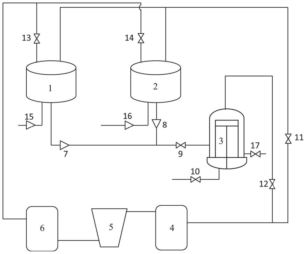
[0060] like figure 1 As shown, a liquefied hydrocarbon storage tank replacement gas recovery device includes a liquefied hydrocarbon storage tank 1 to be detected, a liquefied hydrocarbon storage tank 2, a liquefied hydrocarbon gasification separator 3, and a liquefied hydrocarbon compressor 5. One end of the liquefied hydrocarbon compressor 5 is connected to The compressor inlet buffer tank 4 is connected, the other end is connected to the compressor outlet buffer tank 6, the liquefied hydrocarbon storage tank 1 to be detected and the top of the liquefied hydrocarbon storage tank 2 are connected to the compressor inlet buffer tank 4, the liquefied hydrocarbon storage tank 1 to be detected and the top of the liquefied hydrocarbon storage tank 2 are connected to the compressor inlet buffer tank 4. The bottom of the liquefied hydrocarbon storage tank 2 is connected to the liquefied hydrocarbon gasification separator 3, and the compressor outlet buffer tank 6 is connected to the l...

Embodiment 2

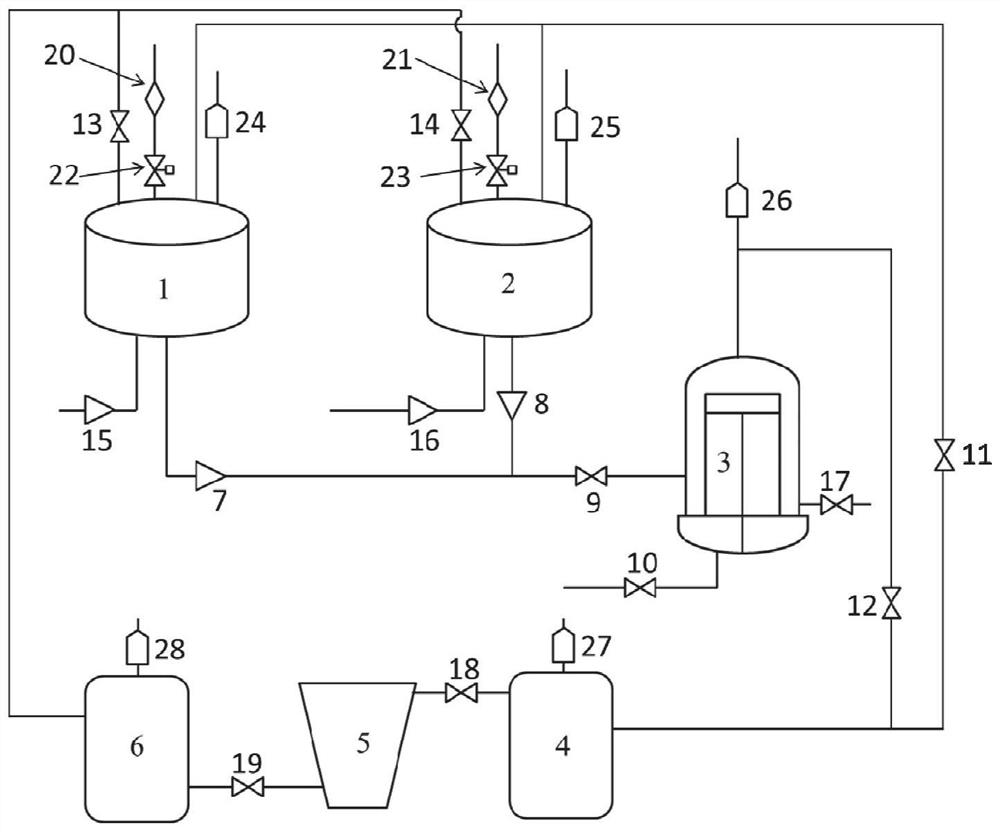
[0064] like figure 2 A liquefied hydrocarbon storage tank replacement gas recovery device shown, comprises a liquefied hydrocarbon storage tank 1 to be detected, a liquefied hydrocarbon storage tank 2, a liquefied hydrocarbon gasification separator 3, a liquefied hydrocarbon compressor 5, and one end of the liquefied hydrocarbon compressor 5 is connected to the compressor. The compressor inlet buffer tank 4 is connected, the other end is connected to the compressor outlet buffer tank 6, the liquefied hydrocarbon storage tank 1 to be detected and the top of the liquefied hydrocarbon storage tank 2 are connected to the compressor inlet buffer tank 4, the liquefied hydrocarbon storage tank 1 to be detected and the liquefied hydrocarbon storage tank 2 are connected to the compressor inlet buffer tank 4. The bottom of the hydrocarbon storage tank 2 is connected to the liquefied hydrocarbon gasification separator 3, and the compressor outlet buffer tank 6 is connected to the liquefi...

Embodiment 3

[0072] A method for recovering replacement gas from a liquefied hydrocarbon storage tank, using the liquefied hydrocarbon storage tank replacement gas recovery device of Embodiment 2 for recovery, including the transfer steps of liquid phase, gas phase, and residual liquid phase.

[0073] The liquid phase transfer step includes: the compressed gas generated by the compressor outlet buffer tank enters the liquefied hydrocarbon storage tank to be detected for pressurization, and the liquefied hydrocarbons in the liquefied hydrocarbon storage tank to be detected are transferred to the liquefied hydrocarbon storage tank;

[0074]The gas phase transfer step includes: the compressor inlet buffer tank extracts the gas phase in the liquefied hydrocarbon storage tank to be detected, and the gas phase is extracted to the liquefied hydrocarbon compressor, and transported to the liquefied hydrocarbon storage tank through the compressor outlet buffer tank;

[0075] The step of transferring ...


PUM


Abstract

The invention relates to the technical field of storage tank replacement and gas recovery, in particular to a liquefied hydrocarbon storage tank replacement and gas recovery device, and a method and an application thereof. The device comprises a liquefied hydrocarbon storage tank to be detected, a liquefied hydrocarbon storage tank, a liquefied hydrocarbon gasification separator, and a liquefied hydrocarbon compressor; one end of the liquefied hydrocarbon compressor is connected with a compressor inlet buffer tank, and the other end is connected with a compressor outlet buffer tank; the tops of the liquefied hydrocarbon storage tank to be detected and the liquefied hydrocarbon storage tank are connected with the compressor inlet buffer tank; the bottoms of the liquefied hydrocarbon storage tank to be detected and the liquefied hydrocarbon storage tank are connected with the liquefied hydrocarbon gasification separator; and the compressor outlet buffer tank is respectively connected with the liquefied hydrocarbon storage tank to be detected and the liquefied hydrocarbon storage tank. Through reasonable design of a connection relationship among the liquefied hydrocarbon storage tank to be detected, the liquefied hydrocarbon storage tank, the liquefied hydrocarbon gasification separator and the liquefied hydrocarbon compressor, liquid phase, gas phase and residual liquid phase transfer of hydrocarbon substances are fully completed. And by arranging a water injection port, liquefied hydrocarbon is prevented from flowing out when accidental leakage occurs.

Description

technical field [0001] The invention relates to the technical field of storage tank replacement gas recovery, in particular to a liquefied hydrocarbon storage tank replacement gas recovery device and a method and application thereof. Background technique [0002] The information disclosed in this Background section is only for enhancement of understanding of the general background of the invention and should not necessarily be taken as an acknowledgement or any form of suggestion that this information forms the prior art already known to a person of ordinary skill in the art. [0003] Liquefied hydrocarbon is one of the basic raw materials of petrochemical industry, which can be used to produce a variety of important organic chemical raw materials, such as liquefied hydrocarbon nitrile, propylene oxide, cumene, butanol, octanol, etc. Since liquefied hydrocarbons are basic raw materials, general chemical companies directly reprocess commercially available liquefied hydrocarbo...

Claims


Application Information

Patent Timeline
IPC IPC(8): F17C7/04F17C13/02F17C13/04F17C13/12
CPCF17C7/04F17C13/02F17C13/04F17C13/12F17C2260/036F17C2260/046F17C2223/013F17C2227/0157
Inventor 李延顺张德厚魏传令王磊荆庆勇王明积
Owner LIAOCHENG MEIWU NEW MATERIAL SCI & TECHCO
Why Eureka
Try Eureka