Quaternion-based sea surface oil spill identification method and system

A recognition method and sea oil spill technology, applied in character and pattern recognition, instruments, analysis materials, etc., can solve the problems of long time-consuming oil spill detection process, high labor cost, not suitable for oil spill accidents, etc., to achieve convenience for human eyes Recognition, realize the effect of object recognition, visual image object recognition

Active Publication Date: 2021-07-30
CHINA UNIV OF PETROLEUM (EAST CHINA)
View PDF6 Cites 1 Cited by
  • Summary
  • Abstract
  • Description
  • Claims
  • Application Information

AI Technical Summary

Problems solved by technology

[0006] The invention mainly solves the technical problems of the prior art, such as long time-consuming oil spill detection process, high labor cost, unsuitable for sudden oil spill accidents, etc., and proposes a sea surface oil spill recognition method and system based on quaternion, which can realize oil film Division of areas and water surfaces and detection of oil spill types

Method used


Image

  • Quaternion-based sea surface oil spill identification method and system
  • Quaternion-based sea surface oil spill identification method and system
  • Quaternion-based sea surface oil spill identification method and system

Examples


Embodiment 1

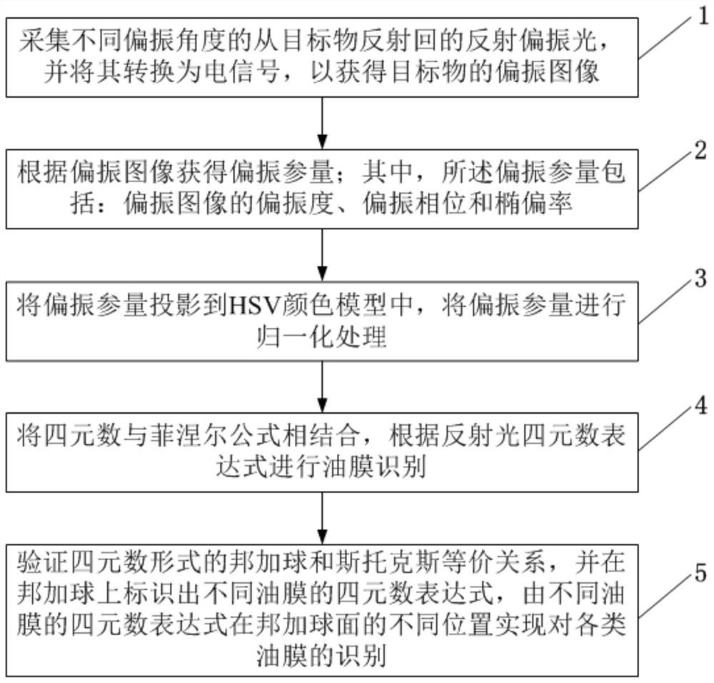
[0105] like figure 1 As shown, the present embodiment provides a method for identifying sea oil spills based on quaternions, including the following processes:

[0106] Step 1: collect the reflected polarized light reflected from the target object at different polarization angles, and convert it into an electrical signal to obtain a polarized image of the target object.

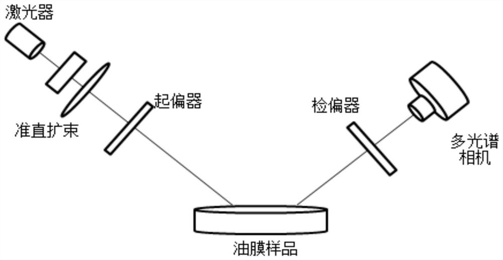
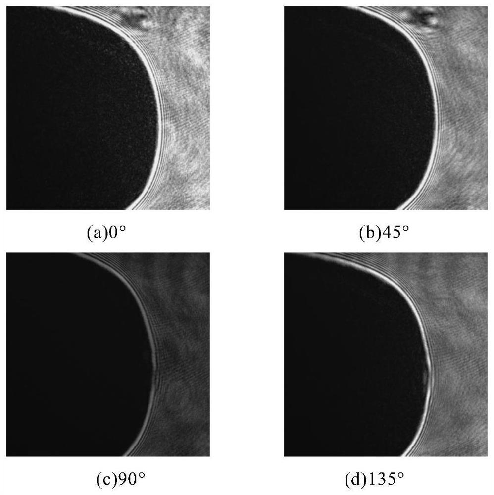
[0107] During this step, the intensity of the light should remain constant as the polarization state of the incident light varies. Therefore, a liquid crystal phase variable retarder (LCVR) is placed after the polarizer, and the conversion of four polarization directions of 0°, 45°, 90° and 135° is realized by adjusting the voltage between the electrodes of the LCVR. The method of this embodiment can be through such as figure 2 The experimental optical path shown is implemented.

[0108] Step 2, obtaining polarization parameters according to the polarization image; wherein, the polarization parameters inc...

Embodiment 2

[0206] like figure 2 As shown, the present invention also provides a quaternion-based sea surface oil spill identification system, including: an experimental light source component, a polarization modulation component, an image acquisition component and an image processing component;

[0207] The experimental light source assembly is used for emitting laser light to the target; the experimental light source assembly adopts a laser; the laser emits a continuous laser with a center wavelength of 632 nm. A collimating beam expander is arranged in the outgoing direction of the laser.

[0208]The polarization modulation component includes: an emission polarization control part and a reflection polarization control part; the emission polarization control part is used to control the polarization angle of the emission polarization; the reflection polarization control part is used to make the The image acquisition component can receive the reflected polarized light of the correspondi...


PUM


Abstract

The invention relates to the field of sea surface oil spill detection, and provides a quaternion-based sea surface oil spill identification method and system. The method comprises the steps of 1, collecting reflected polarized light reflected from a target object at different polarization angles, and converting the reflected polarized light into an electric signal, so as to obtain a polarization image of the target object, 2, obtaining a polarization parameter according to the polarization image, 3, projecting the polarization parameters into an HSV color model, and conducting normalization processing on the polarization parameters, 4, combining the quaternion with a Fresnel formula, and performing oil film identification according to a reflected light quaternion expression, and 5, verifying the equivalence relationship between the quaternion-form Poincare ball and Stokes, marking quaternion expressions of different oil films on the Poincare ball, and realizing identification of various oil films at different positions of the Poincare ball surface by the quaternion expressions of different oil films. Division of an oil film area and a water surface and identification and detection of types of spilled oil can be realized.

Description

technical field [0001] The invention relates to the field of sea surface oil spill detection, in particular to a method and system for sea surface oil spill identification based on quaternion. Background technique [0002] With the rapid development of the world economy, the demand for petroleum energy in various countries has increased year by year, and industries such as oil exploration and transportation have developed more and more rapidly. At the same time, the probability of oil spill accidents in the process of oil exploration and transportation has also increased. When an oil spill occurs, in addition to the release of harmful gases such as aromatic hydrocarbon compounds, an oil film will form on the sea surface, resulting in lack of oxygen in large areas of the sea, a large number of marine organisms die, and the marine ecological environment is severely damaged. In 1983, the successful development of imaging spectrometers made hyperspectral detectors widely used. T...

Claims


Application Information

Patent Timeline
IPC IPC(8): G01N21/21G06K9/00
CPCG01N21/211G06V20/00
Inventor 李代林龙霖吴子豪
Owner CHINA UNIV OF PETROLEUM (EAST CHINA)
Why Eureka
Try Eureka