Electricity utilization safety monitoring system and method

A technology of safety monitoring and leakage current, applied in information technology support system, short-circuit test, electrical components, etc., can solve the problems of complex electric field distribution, geometric area and distance of immersed parts of electrical appliances, etc.

Inactive Publication Date: 2021-07-30
弗瑞斯科应急技术(江苏)有限公司
View PDF0 Cites 1 Cited by
  • Summary
  • Abstract
  • Description
  • Claims
  • Application Information

AI Technical Summary

Problems solved by technology

Since the geometric area and distance of the submerged part of the electrical appliance are difficult to measure, the electric field distribution in the water body is very complicated

Method used


Image

  • Electricity utilization safety monitoring system and method
  • Electricity utilization safety monitoring system and method
  • Electricity utilization safety monitoring system and method

Examples


Embodiment 1

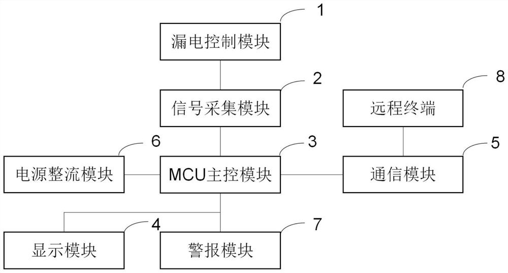
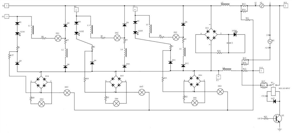
[0076]When the leakage control module 1 is connected to a three-phase four-wire three-phase power supply, the terminals A1, B1, C1 and N1 of the leakage control module 1 are connected in parallel to the live wires A, B, C and neutral wires of the three-phase power supply in sequence. N. Generally, the three-phase power supply equipment needs a grounding wire when it is connected to electricity, and the grounding wire is generally connected to the shell of the equipment. In this device, the other end of the grounding wire can be connected to the equipment grounding terminal FG1; the grounding terminal E1 in the leakage control module 1 The floating ground terminal FG2 can be selected according to the actual situation. Under normal circumstances, the ground terminal E1 is selected, and the ground terminal E1 is directly buried in the ground to facilitate drainage to the ground.

[0077] When the system is in normal use, the terminals A1, B1, and C1 of the leakage control module ...

Embodiment 2

[0079] When the leakage control module 1 is connected to the two-phase power supply, the terminals A1 and N1 of the leakage control module 1 are sequentially connected in parallel to the live line L and the neutral line N of the two-phase power supply. Generally, high-power equipment needs a grounding wire when it is connected to electricity, and the grounding wire is generally connected to the shell of the equipment. In this device, the other end of the grounding wire can be connected to the equipment grounding terminal FG1; the grounding terminal E1 in the leakage control module 1 The floating ground terminal FG2 can be selected according to the actual situation. Under normal circumstances, the ground terminal E1 is selected, and the ground terminal E1 is directly buried in the ground to facilitate drainage to the ground.

[0080] When the system is in normal use, the terminals A1 and N1 of the leakage control module 1 will rectify and discharge the two-phase current through ...


PUM


Abstract

The invention discloses an electricity utilization safety monitoring system and method. The electricity utilization safety monitoring system comprises an electric leakage control module, a signal acquisition module, an MCU main control module, a display module, a communication module, a power supply rectification module, an alarm module and a remote terminal. According to the invention, the wire inlet port of the leakage control module is connected in parallel to the live wire end and the zero wire end of the power supply, so that the installation is convenient, and no influence is generated to the power supply of the operation equipment; the system is provided with multiple leakage protections, leakage current can be displayed on the display module when the leakage current detection circuit detects a leakage current value of an equipment grounding end, and when the leakage current value exceeds a safety value, current can be directly led to the grounding end and a zero line end through the current acquisition chip, so that the equipment surface is reduced to a position which cannot hurt a human body; electric leakage equipment can be processed in time; and the wireless communication module is arranged, so that leakage current of the equipment can be fed back to production management personnel in time, and safety monitoring on each piece of production equipment is facilitated.

Description

technical field [0001] The invention relates to the technical field of circuit safety, in particular to an electricity safety monitoring system and method. Background technique [0002] my country's low-voltage civilian electricity is AC three-phase four-wire system 50Hz, the voltage between the three phase lines L1, L2 and L3 is 380V (effective value), and the phase difference is 120 。 . [0003] The voltage between the three phase lines and the neutral line N is 220V (effective value). Among them, the neutral line N is reliably connected to the ground at the substation using a physical method. Therefore, whether it is a three-phase 380V application (L1 / L 2 / L3 / N) in an industrial environment or a single-phase 220V application (L / N) in a lighting environment, in fact, all phase lines form a loop to the ground. Once the human body touches any phase wire or electrical equipment that leaks electricity, the current will pass through the human body and the ground on which the ...

Claims


Application Information

Patent Timeline
Patent Type & Authority Applications(China)
IPC IPC(8): H02J13/00G01R31/52H02H3/34H02H3/08
CPCG01R31/52H02H3/083H02H3/34H02J13/00001H02J13/00002H02J13/00022H02J13/0004Y02E60/00Y04S40/126
Inventor 朱峰周海涛张正华
Owner 弗瑞斯科应急技术(江苏)有限公司
Why Eureka
Try Eureka