
A wireless charging device with heat preservation function and control method

A wireless charging and functional technology, applied in the direction of electric heating devices, circuit devices, battery circuit devices, etc., can solve the problems of violating the original purpose of wireless chargers, poor versatility, and high heat generation of wireless chargers

Active Publication Date: 2021-09-10
SHENZHEN INJOINIC TECH
View PDF0 Cites 0 Cited by
  • Summary
  • Abstract
  • Description
  • Claims
  • Application Information

AI Technical Summary

Problems solved by technology

[0007] 1. The first solution is relatively safe, but its versatility is very poor. You can only use the matching cup. Even if you use the same kind of cup to heat, the resonant frequency of the whole system of the wireless charger plus the cup will change. However, the transmission frequency used remains unchanged, resulting in low heating efficiency, high energy consumption, and high heat generation of the wireless charger itself.
[0008] 2. The second solution is slightly more versatile, but the security risks are very obvious
The way to identify the cup is doomed that these products cannot recognize other metal objects with the same metal properties, such as iron pans, mobile phones or other electrical appliances. As long as such large metal objects are put in, they will send power to them, which violates wireless charging. The original purpose of detecting foreign objects in the device, and the battery may be heated to explode due to the mobile phone entering the heating mode by mistake, which will bring serious safety hazards

Method used


Image

  • A wireless charging device with heat preservation function and control method
  • A wireless charging device with heat preservation function and control method
  • A wireless charging device with heat preservation function and control method

Examples


Embodiment Construction

[0034] In order to make the purpose, technical solutions and advantages of the embodiments of the present invention more clear, the following will clearly and completely describe the technical solutions of the embodiments of the present invention in conjunction with the drawings of the embodiments of the present invention. Apparently, the described embodiments are some, not all, embodiments of the present invention. Based on the described embodiments of the present invention, all other embodiments obtained by persons of ordinary skill in the art without creative efforts shall fall within the protection scope of the present invention.

[0035] An embodiment of a wireless charging device with heat preservation function:

[0036] A wireless charging device with heat preservation function of the present invention comprises a carrier capable of carrying objects, a wireless charging unit arranged on the carrier and electrically connected to an external power source to generate a mag...


PUM


Abstract

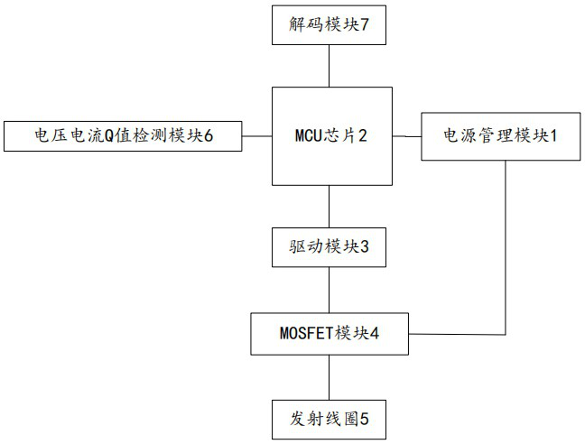
The present invention provides a wireless charging device with heat preservation function and a control method. The switch includes a carrier capable of carrying placed objects, which is arranged on the carrier and can be electrically connected to an external power source, so that the wireless charging unit generates a magnetic field at the carrier. And a placed object detection unit arranged on the carrier, the placed object detection unit is set to whether there is a placed object placed on the carrier; the wireless charging unit includes a transmitting unit and a receiving unit, and the transmitting unit includes a power management module and an MCU that can output PWM signals A chip, a drive module for driving the MOSFET device, connected to the drive module, a MOSFET module, a transmitting coil, a voltage and current Q value detection module, and a decoding module. The method of the present invention is applied to the above wireless charging device. The present invention can solve potential safety hazards in most use scenarios, can achieve higher heating efficiency and reduce the heat generated by the wireless charger itself, and has both safety and versatility.

Description

technical field [0001] The invention relates to the technical field of wireless charging, in particular to a wireless charging device with heat preservation function and a control method applied to the device. Background technique [0002] A wireless charger is a device that uses the principle of electromagnetic induction to transmit energy and supply it to a receiving end (smartphone, smart watch, TWS Bluetooth headset, etc.) equipped with a wireless charging function. The energy sent during wireless charging can not only charge the receiving end, but also heat the metal placement. The traditional wireless charging heating system can only heat specific cups with receiving coils and has poor versatility, or can heat most cups but cannot distinguish metal foreign objects from cups, resulting in poor safety. At present, there is no wireless charging heating product with both versatility and safety in the market. [0003] At present, there are roughly two wireless charger sol...

Claims


Application Information

Patent Timeline
Patent Type & Authority Patents(China)
IPC IPC(8): H02J50/60H02J7/00H05B6/10
CPCH02J7/0044H05B6/101H05B6/105H02J50/60
Inventor 陈卫曾令宇成海鹏
Owner SHENZHEN INJOINIC TECH
Learn More