Container type solar panel unfolding device

A solar panel, containerized technology, applied in the field of containerized solar panel deployment devices, can solve the problems of unfavorable small individual power generation, large floor space, poor flexibility, etc. Effect

Pending Publication Date: 2021-07-30
TONGJI UNIV
View PDF7 Cites 1 Cited by
  • Summary
  • Abstract
  • Description
  • Claims
  • Application Information

AI Technical Summary

Problems solved by technology

Large area, concentrated power generation, easy to damage in extreme weather, poor flexibility, not conducive to small individual power generation

Method used


Image

  • Container type solar panel unfolding device
  • Container type solar panel unfolding device
  • Container type solar panel unfolding device

Examples


Embodiment

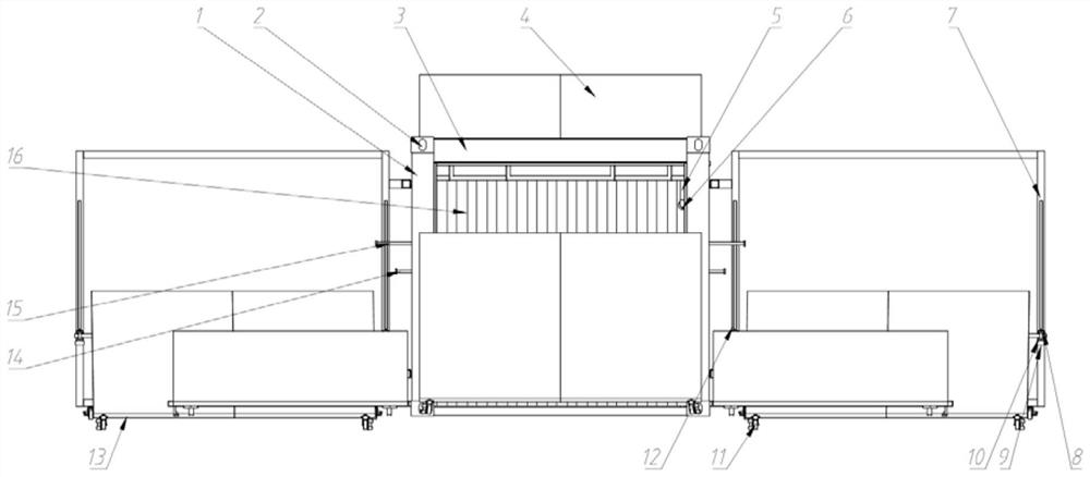
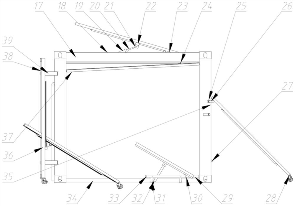
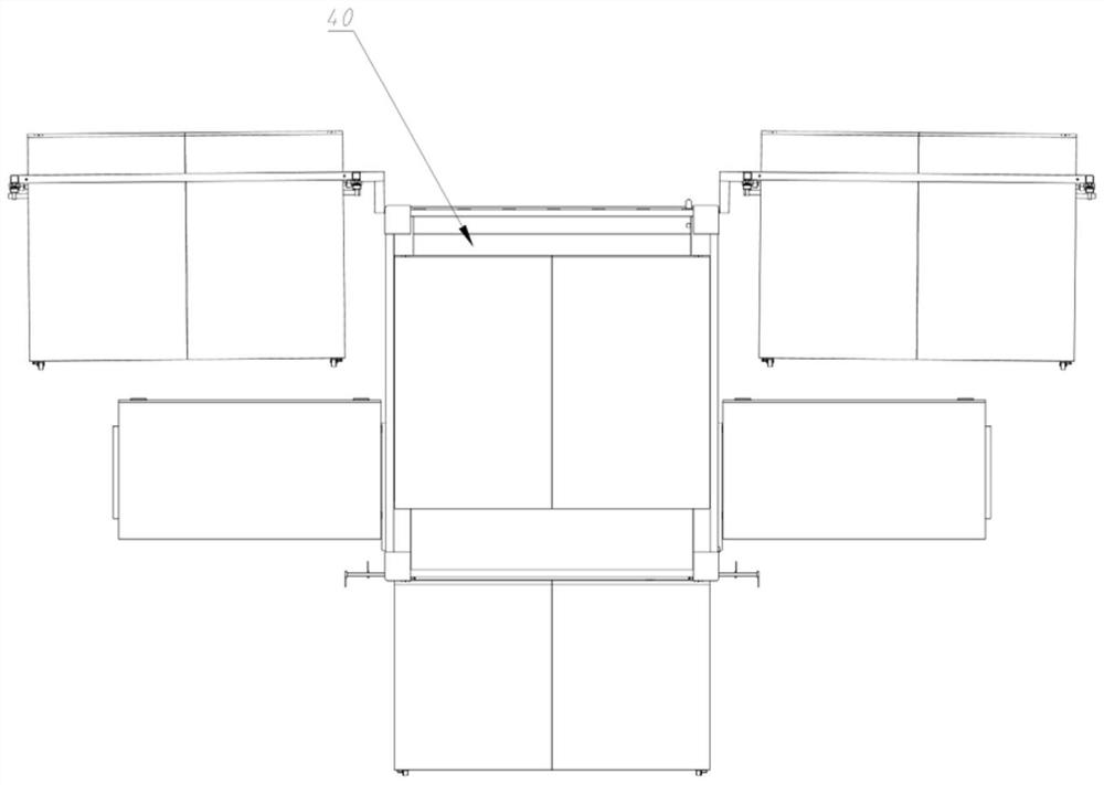
[0030] Such as Figure 1~4 As shown, a container-type solar panel deployment device, the device uses a container frame as a base, and the container frame includes 2 parallel top beams 3, 2 parallel top side beams 17, 2 parallel bottom beams, 2 parallel bottom side beams and 4 vertical columns 1, the top beam 3 and the top side beam 17 form a square structure, correspondingly, the bottom beam and the bottom side beam form a square structure, and the top and bottom direction structures are passed through the vertical Uprights 1 are supported and connected by corner fittings 2 . A rear side panel 16 is provided on the rear side of the container frame.

[0031] The container-type solar panel unfolding device includes several solar panel units, each solar panel unit is directly or indirectly connected to the base body through moving parts, when unfolded, each solar panel unit is unfolded to the outside of the base body, and when recycled, each solar panel unit is folded toward the...


PUM


Abstract

The invention relates to a container type solar panel unfolding device which takes a container frame body as a base body and comprises a plurality of solar panel units. Each solar panel unit is directly or indirectly connected with a base body through a moving part. When the solar panel units are unfolded, the solar panel units are unfolded towards the outer side of the base body; and when the solar panel units are folded, the solar panel units are folded towards the base body to form a container shape. Compared with the prior art, the container is used as a base body, opening and closing are convenient, flexibility is good, transportation is convenient, and sufficient power supply can be provided in places where a power network cannot reach.

Description

technical field [0001] The invention relates to the field of photovoltaic power generation, in particular to a container-type solar panel deployment device. Background technique [0002] The main way to use solar energy today is to convert it into secondary energy electricity with a wide range of utilization. Photovoltaic power generation is the main way to convert solar energy into electrical energy. The principle is to use semiconductors (more commonly polycrystalline silicon or monocrystalline silicon), through The photoelectric effect converts light energy directly into electrical energy for utilization. [0003] At present, most of the ways of solar power generation at home and abroad are in the form of fixed solar photovoltaic panel arrays. It covers a large area and generates electricity intensively. It is easy to be damaged in extreme weather and has poor flexibility, which is not conducive to power generation by small individuals. Contents of the invention [00...

Claims


Application Information

Patent Timeline
Patent Type & Authority Applications(China)
IPC IPC(8): H02S20/30H02S30/10H02S30/00F24S30/40
CPCH02S20/30H02S30/10H02S30/00F24S30/40Y02E10/47Y02E10/50
Inventor 孙波李帆陈培正覃栋鹏袁九海奚鹰
Owner TONGJI UNIV
Why Eureka
Try Eureka