Intelligent agricultural seeder capable of rapidly changing spacing
A seeder, agricultural technology, applied in agriculture, sowing, planter parts, etc., can solve the problems of corn harvesting, yield reduction, fixed row spacing, and inability to adjust row spacing.
- Summary
- Abstract
- Description
- Claims
- Application Information
AI Technical Summary
Problems solved by technology
Method used
Image

Examples
Embodiment 1
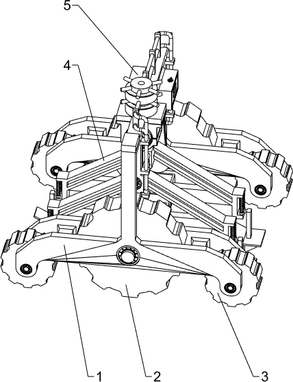
[0031] A fast-changing seeder for smart agriculture, such as figure 1 and figure 2As shown, it includes a vehicle frame 1, a first traveling wheel 2, a second traveling wheel 3, a wireless module 31, a seeding mechanism 4 and a power mechanism 5, and the lower parts of the front and rear sides of the vehicle frame 1 are equipped with first traveling wheels through bearings. 2. The front and rear two first traveling wheels 2 are arranged symmetrically. The frame 1 on the left and right sides of the first traveling wheel 2 is equipped with the second traveling wheel 3 through bearings, and a wireless module 31 is installed on the top front side of the frame 1. A sowing mechanism 4 is installed between the front and rear side walls in the vehicle frame 1. The sowing mechanism 4 is located between the front and rear two first running wheels 2. A line connection is provided between the sowing mechanism 4 and the wireless module 31. On the sowing mechanism 4 The vehicle frame 1 of...
Embodiment 2
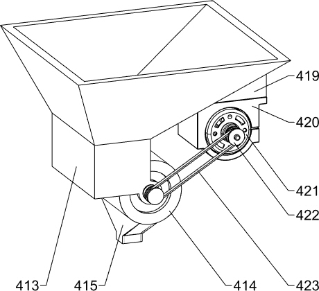
[0034] On the basis of Example 1, as Figure 3 to Figure 7 As shown, the seeding mechanism 4 includes a first guide rod 401, a first slide plate 402, a second slide plate 403, an inclined frame 404, a second guide rod 405, a slide frame 406, a return spring 407, a baffle plate 408, an inclined push Plate 409, spacer plate 410, plowshare 411, holding frame 412, lower material box 413, lower material cylinder 414, discharge hopper 415, rotating roller 416, first belt pulley 418 and power components, two front and rear in vehicle frame 1 Two first guide rods 401 are installed between the side walls, and the two first guide rods 401 are arranged symmetrically up and down. A first sliding plate 402 and a second sliding plate 403 are slidably arranged between a guide bar 401, and the left and right side walls of the first sliding plate 402 and the second sliding plate 403 are fixedly connected with a tilting frame 404, and the tilting frame 404 The lower part is fixed with two seco...
Embodiment 3
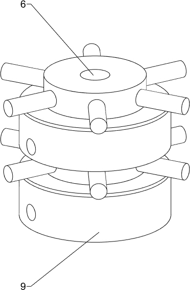
[0043] On the basis of Example 2, such as Figures 12 to 14, also includes a fixed rod 6, a winding reel 7, a grip rod 8, a housing 9, a first support plate 10, a first conduit 11, a second support plate 12, a second conduit 13, a third conduit 14, The first steel wire rope 15 and the second steel wire rope 16, the top of the vehicle frame 1 on the rear side of the wireless module 31 is equipped with a fixed rod 6, the upper and lower sides of the fixed rod 6 are equipped with a winding reel 7 through bearings, and the circumferential wall of the winding reel 7 The upper part is evenly spaced with at least three grip bars 8, and the upper part of the outer wall of the winding reel 7 is rotatably installed with a casing 9, and the casings 9 are respectively located on the lower side of the corresponding grip bars 8, and the top of the vehicle frame 1 on the rear side of the fixed rod 6 There are three first support plates 10 fixedly connected, and first conduits 11 are embedded...
PUM
 Abstract
Description
Claims
Application Information
 - R&D
- Intellectual Property
- Life Sciences
- Materials
- Tech Scout
- Unparalleled Data Quality
- Higher Quality Content
- 60% Fewer Hallucinations
Browse by: Latest US Patents, China's latest patents, Technical Efficacy Thesaurus, Application Domain, Technology Topic, Popular Technical Reports.
© 2025 PatSnap. All rights reserved.Legal|Privacy policy|Modern Slavery Act Transparency Statement|Sitemap|About US| Contact US: help@patsnap.com