Wrist turning mechanism and surgical robot

A technology of surgical robot and rotation axis, which is applied in the field of medical devices, can solve the problems of flexible adjustment of end tools, difficult adjustment of jaw direction, cross-infection, etc., to avoid repeated cleaning and sterilization and cross-infection, simplify assembly process, The effect of reducing the number of parts

Pending Publication Date: 2021-08-03
RONOVO (SHANGHAI) MEDICAL SCI & TECH LTD
View PDF9 Cites 0 Cited by
  • Summary
  • Abstract
  • Description
  • Claims
  • Application Information

AI Technical Summary

Problems solved by technology

Excluding the degree of freedom of jaw opening and closing, the end tool and the shaft section of the instrument are relatively fixed. Although the operator can manipulate the instrument to move the tool to the desired position, since the shaft section of the instrument has only one degree of freedom of rotation (for example, the end tool rotates around the shaft section rotational freedom on its own axis), the orientation of the jaws relative to the tissue is difficult to adjust
For example, in the closure of blood vessels, the end tool needs to close the lumen laterally along the blood vessel, while traditional laparoscopic instruments are often difficult to achieve flexible adjustment of the angle of the end tool due to the limitation of the approach and the operating space of the abdominal cavity
[0003] In order to realize the rotation of the jaws relative to the axis of the instrument, a wrist-rotating instrument is proposed in the prior art. This wrist-rotating instrument adopts the structure of a cable and a pulley, which has problems such as complicated design and high cost.
In order to reduce costs, this wrist-rotating device adopts the design and use method of repeated use and multiple cleaning and sterilization, which also brings additional risks of cross-infection

Method used


Image

  • Wrist turning mechanism and surgical robot
  • Wrist turning mechanism and surgical robot
  • Wrist turning mechanism and surgical robot

Examples


Embodiment approach 1

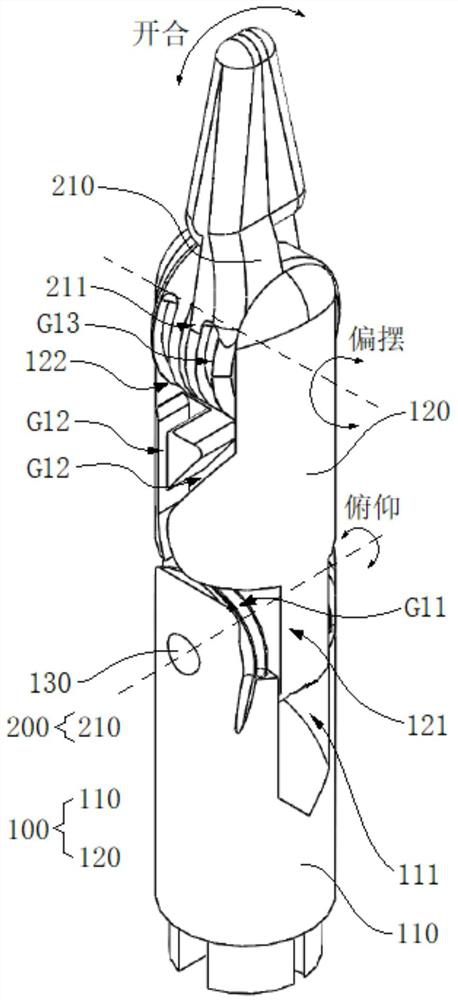
[0056] refer to figure 1 , which typically shows a perspective view of the wrist rotation mechanism proposed by the present invention. In this exemplary embodiment, the wrist rotation mechanism proposed by the present invention is described by taking related instruments applied to laparoscopic surgery as an example. Those skilled in the art can easily understand that, in order to apply the relevant design of the present invention to other types of medical devices, various modifications, additions, substitutions, deletions or other changes are made to the following specific embodiments, these Variations are still within the scope of the principles of the wrist mechanism proposed by the present invention.

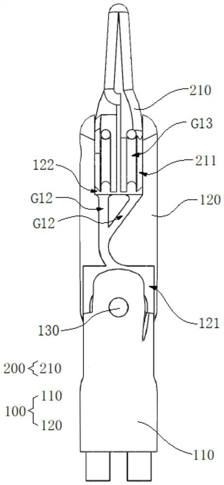
[0057] like figure 1 As shown, in this embodiment, the wrist rotation mechanism proposed by the present invention includes a bracket, an end tool and a cable. Cooperate with reference Figure 2 to Figure 6 , figure 2 representatively shows a front view of a wrist rotati...

Embodiment approach 2

[0076] Based on the above detailed description of the first embodiment of the wrist rotation mechanism proposed by the present invention, the following will be combined Figure 7 to Figure 10 , the second embodiment of the wrist rotation mechanism proposed by the present invention will be described. like Figure 7 to Figure 10 as shown, Figure 7 representatively shows a perspective view of the second embodiment of the wrist rotation mechanism proposed by the present invention; Figure 8 Representatively shows an exploded schematic view of the wrist rotation mechanism in the second embodiment; Figure 9 representatively shows a perspective view of the first bracket of the wrist rotation mechanism in the second embodiment; Figure 10 representatively shows Figure 9 A cross-sectional view of the first stent is shown. The main differences between the second embodiment and the first embodiment of the wrist rotation mechanism proposed by the present invention will be describe...

Embodiment approach 3

[0085] Based on the above detailed description of the second embodiment of the wrist rotation mechanism proposed by the present invention, the following will be combined Figure 11 , the third embodiment of the wrist rotation mechanism proposed by the present invention will be described. like Figure 11 as shown, Figure 11 is a representative perspective view of the first bracket of the wrist rotation mechanism in the third embodiment. The main differences between the third embodiment and the second embodiment of the wrist rotation mechanism proposed by the present invention will be described below with reference to the above-mentioned drawings.

[0086] like Figure 11 As shown, in this embodiment, the guide groove at the proximal end of the first bracket 110 can be directly formed by an arc-shaped surface, that is, the surface of the arc-shaped surface 112 can be used to guide the cable 300 . In other embodiments, such as the second embodiment, the guide groove G21 at t...


PUM


Abstract

The invention provides a wrist turning mechanism and a surgical robot. The wrist turning mechanism comprises a support, a tail end tool and a mooring rope. The support is provided with at least two pairs of guide grooves and comprises a first support and a second support, the near end of the second support is rotatably connected to the far end of the first support, and the guide grooves of the support are formed in at least one of the first support and the second support; the tail end tool is rotatably connected to the far end of the second support, and a guide groove is formed in the tail end tool; and the mooring rope is arranged along the guide groove of the support and the guide groove of the tail end tool and used for driving the tail end tool to achieve pitching motion and deflection motion. By means of the design, the rotation freedom degree of the tail end tool relative to the support is increased, and the tail end tool has the angle adjusting function. Compared with an existing mechanism, the wrist rotating mechanism adopts the guide groove to replace a pulley and other structures, the number of parts is reduced, the assembly process is simplified, and therefore cost is greatly reduced, and disposable use of instruments is achieved.

Description

technical field [0001] The invention relates to the technical field of medical instruments, in particular to a wrist rotation mechanism and a surgical robot. Background technique [0002] In operations such as laparoscopic surgery, conventional instruments are straight cylinders, and operating tools are mounted on the ends of the straight cylinders. The tools described above consist of opposing jaws that grip tissue and clamp blood vessels. The jaws are somehow held together to close and open. Excluding the degree of freedom of jaw opening and closing, the end tool and the shaft section of the instrument are relatively fixed. Although the operator can manipulate the instrument to move the tool to the desired position, since the shaft section of the instrument has only one degree of freedom of rotation (for example, the end tool rotates around the shaft section rotational freedom of its own axis), the orientation of the jaws relative to the tissue is difficult to adjust. F...

Claims


Application Information

Patent Timeline
Patent Type & Authority Applications(China)
IPC IPC(8): A61B34/30A61B17/28A61B17/12
CPCA61B34/30A61B34/71A61B17/28A61B17/12A61B2034/301A61B2034/302A61B2034/305
Inventor 孙晓文毛颖其他发明人请求不公开姓名
Owner RONOVO (SHANGHAI) MEDICAL SCI & TECH LTD
Why Eureka
Try Eureka