
A filter pipe mesh plate grille

A filter pipe network and filter pipe technology, applied in the direction of filtration and separation, fixed filter element filter, separation method, etc., can solve the problems of reducing grid resistance coefficient, frequent equipment failures, performance degradation, etc. surface, improve the service life, and reduce the production cost.

Active Publication Date: 2022-07-12
JIANGSU ZHAOSHENG ENVIRONMENTAL PROTECTION TECH CO LTD
View PDF0 Cites 0 Cited by
  • Summary
  • Abstract
  • Description
  • Claims
  • Application Information

AI Technical Summary

Problems solved by technology

[0006] Going back to the original point, the original intention of the design of the screen grid is to provide elements of high interception rate for the grid equipment through the two-dimensional structure of the screen, which is a clever choice. The resistance coefficient is also a very good design. Such a design can significantly increase the unit processing capacity of the equipment in theory without changing the channel parameters. Then the question arises, why is the metal through-hole mesh plate processed in the actual use process? The water efficiency is not consistent with the theoretical data, sometimes even worse; there is only one explanation, the clogging of the mesh leads to performance degradation; why the equipment still has frequent failures despite the configuration of a variety of slag cleaning devices, regardless of the low price leads to low quality In this case, the main problem should be the slag removal method of the stencil
After careful comparison, it can be found that backwashing is the main method to clean the stencil, but when there are many hairs and fibers in the sewage, the kinetic energy of water backwashing is obviously weaker than that of mechanical brushes, which can also be clearly distinguished from the data. The same model The general power of the equipment using backwashing is 5.5kW, but the power of the mechanical brush is 1.5kW. Not only the energy consumption is several times different, but also the efficiency is the same. Using backwashing alone requires the device to work continuously, but the same situation Next, the working time of the mechanical brush is less than half of the running time of the equipment. This is a good comparison and provides a good direction and idea for the new design of new equipment;

Method used


Image

  • A filter pipe mesh plate grille
  • A filter pipe mesh plate grille
  • A filter pipe mesh plate grille

Examples


Embodiment 1

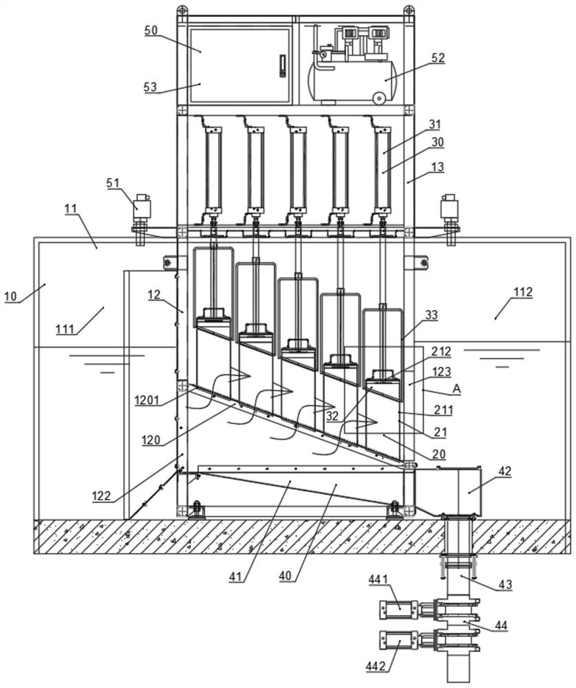
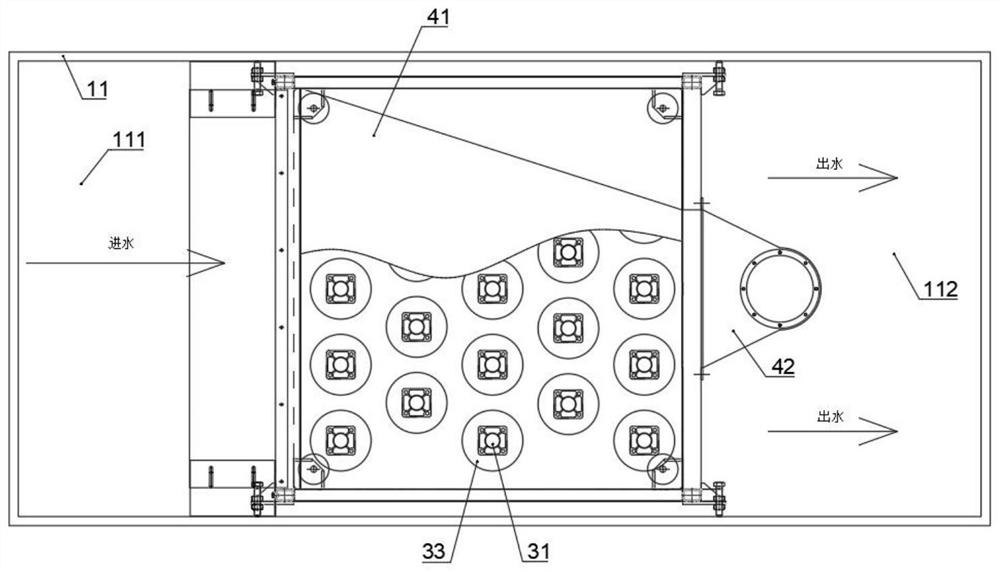
[0055] A filter pipe mesh plate grid, such as figure 1 As shown, it includes a frame 10, a filter tube assembly 20, a slag cleaning assembly 30, a slag discharge assembly 40 and a monitoring and control unit 50;

[0056] like figure 1 As shown, the rack 10 includes a total accommodating shell 11, a filter shell 12 is fixed in the overall accommodating shell 11, and a water-passing inclined plate 120 is fixed in the filter shell 12, and the water-passing inclined plate 120 has a a plurality of water through holes 1201 penetrating up and down;

[0057] The included angle between the water-passing inclined plate 120 and the horizontal is 20°;

[0058] like figure 1 As shown, the side of the sloping plate 120 close to the water inlet silo 111 is higher than the side close to the water outlet silo 112;

[0059] like figure 1 As shown, a water inlet silo 111 is formed between the left side wall of the filter shell 12 and the left inner wall of the total accommodating shell 11 ,...

Embodiment 2

[0076] The difference from Embodiment 1 is that the included angle between the water-passing inclined plate 120 and the horizontal is 50°;

[0077] The inclination angle of the bottom of the slag discharge accommodating shell 41 is 30°;

[0078] The slag discharge pipe 43 at the connection of the slag discharge pneumatic valve 442 has a certain angle with the vertical direction, and the angle range is 90°;

[0079] The filtered water outlet hole 211 is a strip through hole;

[0080] The controller 53 adopts a single chip controller.

Embodiment 3

[0082] The difference from Embodiment 1 is that the angle between the water-passing inclined plate 120 and the horizontal is 30°;

[0083] The inclination angle of the bottom of the slag discharge accommodating shell 41 is 20°;

[0084]The slag discharge pipe 43 at the connection of the slag discharge pneumatic valve 442 has a certain angle with the vertical direction, and the angle range is 45°;

[0085] The filtered water outlet hole 211 is a round hole-shaped through hole;

[0086] Described controller 53 adopts PLC controller;

[0087] In the actual application process of the present invention, the water body to be treated enters from the water inlet bin 111 , and the water body to be treated in the water inlet bin 111 enters the filter shell 12 through the water inlet port 122 at the The part below the water-passing inclined plate 120, and then the water to be treated enters the filter tube 21 through the water-passing hole 1201. After the filter tube 21 filters the wat...


PUM


Abstract

The invention discloses a filter pipe mesh plate grid, comprising a frame, a filter tube assembly, a slag cleaning assembly, a slag discharge assembly and a monitoring and control unit; the frame includes a general accommodating shell, and a general accommodating shell is fixed in the general accommodating shell. a filter shell, a water-passing inclined plate is fixed in the filter shell, and the water-passing inclined plate is provided with a plurality of water passing holes that pass through up and down; the filter tube assembly comprises a Filter tube; fixed filter tube, which reduces the conventional filter screen surface and reduces the cost of the equipment; the filter tube is fixed type, without drive and chain transmission structure, avoids motion wear and improves the operation stability of the equipment, adopts mechanical The mechanical slag cleaning structure and the stencil are vertical shearing motion, which has a good cutting effect on the slag on the stencil surface, which can effectively prevent the slag from gathering and entangled, and improve the equipment. processing efficiency.

Description

technical field [0001] The invention relates to the technical field of sewage treatment, in particular to a filter pipe mesh plate grid. Background technique [0002] In order to adapt to the continuous improvement of the current sewage treatment process, the grille of the pretreatment section has also been continuously improved with the improvement of the index. The mesh plate grille equipment is one of the main equipment. By providing better interception efficiency, sewage The screen slag is separated efficiently, realizing the purpose of sewage pretreatment and protecting the stable operation of the subsequent process equipment of sewage treatment; [0003] Existing mesh grilles, whether imported or domestically produced, generally use double-sided chains to drive the filter mesh plate assembly for rotary motion to filter the slag from the sewage; Due to the mixed state of water and screen slag, an external high dewatering press is generally required; the mesh plate grid...

Claims


Application Information

Patent Timeline
Patent Type & Authority Patents(China)
IPC IPC(8): B01D29/35B01D29/52B01D29/60B01D29/64B01D29/94
CPCB01D29/35B01D29/52B01D29/605B01D29/60B01D29/94B01D29/6484Y02W10/37
Inventor 荣杰尹曙辉
Owner JIANGSU ZHAOSHENG ENVIRONMENTAL PROTECTION TECH CO LTD
Learn More